 Easy Circuits
This article describes a simple LED tester that can be constructed using an LED, a 9V battery, wires, and a small junction box.
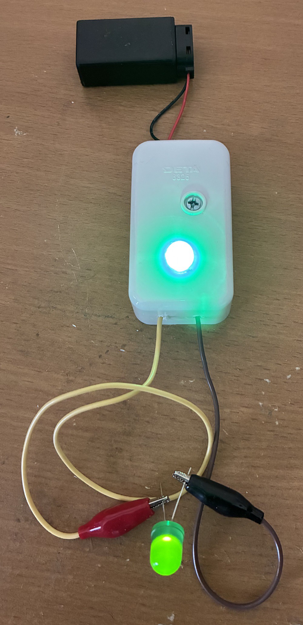
The circuit LED indicator turns ON when an LED is connected. You can see the circuit used to test a red blinking LED in this video:
We all know that a typical LED (Light-Emitting Diode) conducts current in only one direction. Thus, to check if the LED is working, the component needs to be correctly connected. The longer LED pin should be connected to the positive (red) crocodile clip.
Step 1: Design the Circuit
I drew the circuit in PSpice Student Edition version 9.1 to save time.

The student edition software did not have an LED component. Thus, I used three diodes in series to model each of the two LEDs (indicator LED and LED under test).
First, we need to find the maximum current across the indicator LED. The maximum current occurs when both crocodile clips are shorted (connected without the LED).
The maximum current is equal to:
ILedMax = (Vs - Vled1) / R
(Where: Vs = Supply Voltage (V),
R = Resistor (shown in circuit diagram) (ohms),
Vled1 = Indicator LED Voltage (V))
= (9 V - 2 V) / 330 ohms
= 7 V / 330 ohms
= 0.02121 A
= 21.2121 mA
The equation can be rearranged to find the required resistor value for the preferred maximum current:
R = (Vs - Vled1) / ILedMax
We can also find the current across the LED during testing.
ILed = (Vs - Vled1 - Vled2) / R
(Where: Vs = Supply Voltage (V), R = Resistor (shown in diagram) (ohms)
Vled1 = Indicator LED Voltage (V) and Vled2 = LED Under Test Voltage (V))
ILed = (9 V - 2 V - 2 V) / 330 ohms
= 5 V / 330 ohms
= 0.01515 A
= 15.1515 mA
The equation can be rearranged to find the required resistor value for the preferred test current:
R = (Vs - Vled1 - Vled2) / ILED
It is important to mention that some LEDs cannot handle currents above 5 mA without damage. This indicator cannot be used to test all LEDs. A more complicated design would involve designing a 2 V power supply for the LED under test with an LM317 adjustable voltage regulator. You can adjust the LM317 IC (integrated circuit) voltage output to 4 V if you want to include the indicator LED as well as the LED under test in your series circuit.
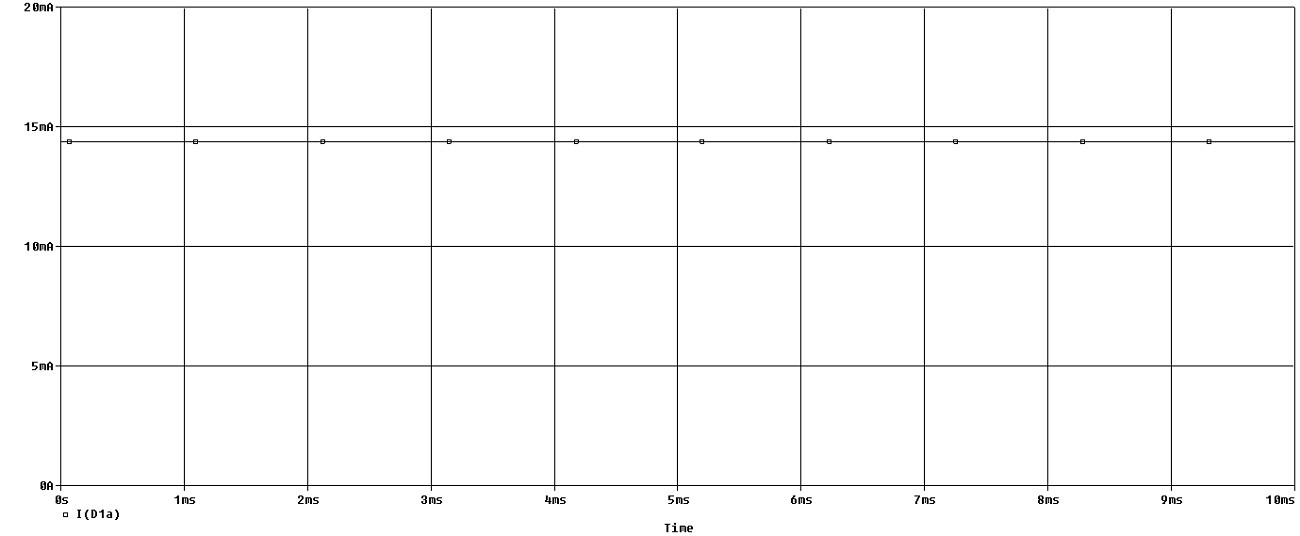
Step 2: Simulations
Simulations show a forward current of almost 15 mA as predicted in the calculations.
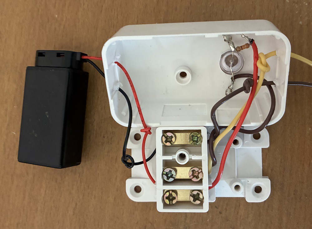
Step 3: Make the Circuit
I used a junction box to connect my circuit. I had to use a soldering iron to connect the 330 ohm resistor to the LED because the junction box did not have enough connectors (this is a standard junction box from a hardware store that has three connectors for active, neutral, and earth).
Step 4: Testing
I used the circuit to test a green LED (non-blinking LED):
Conclusion
This article shows you how to design and make a simple LED tester.
Discussions
Become a Hackaday.io Member
Create an account to leave a comment. Already have an account? Log In.