 Easy Circuits
-
LED Tester
11/05/2025 at 05:47 • 0 commentsThis article describes a simple LED tester that can be constructed using an LED, a 9V battery, wires, and a small junction box.
![]()
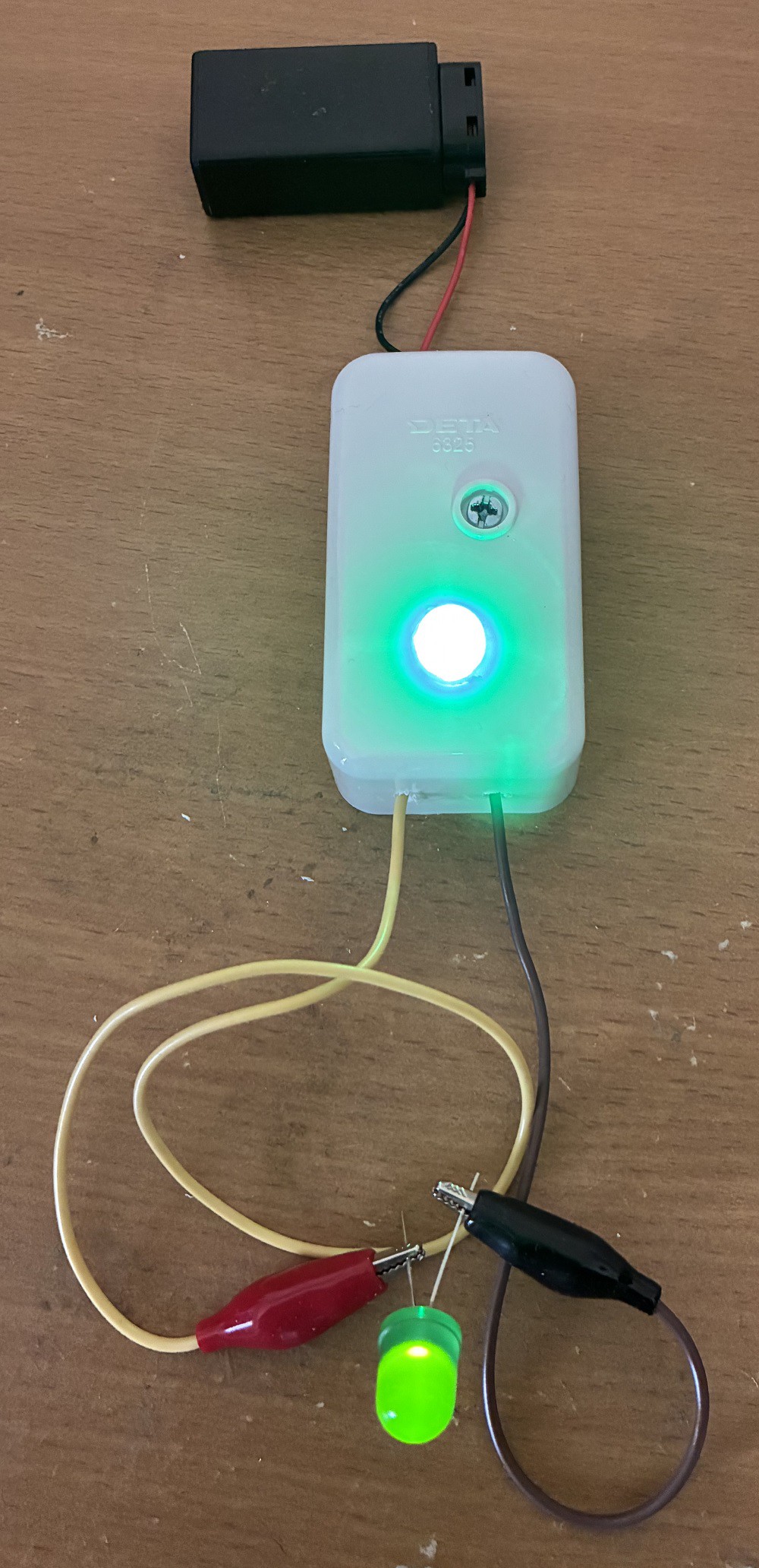
The circuit LED indicator turns ON when an LED is connected. You can see the circuit used to test a red blinking LED in this video:
We all know that a typical LED (Light-Emitting Diode) conducts current in only one direction. Thus, to check if the LED is working, the component needs to be correctly connected. The longer LED pin should be connected to the positive (red) crocodile clip.
Step 1: Design the Circuit
I drew the circuit in PSpice Student Edition version 9.1 to save time.
![]()
The student edition software did not have an LED component. Thus, I used three diodes in series to model each of the two LEDs (indicator LED and LED under test).
First, we need to find the maximum current across the indicator LED. The maximum current occurs when both crocodile clips are shorted (connected without the LED).
The maximum current is equal to:
ILedMax = (Vs - Vled1) / R
(Where: Vs = Supply Voltage (V),
R = Resistor (shown in circuit diagram) (ohms),
Vled1 = Indicator LED Voltage (V))
= (9 V - 2 V) / 330 ohms
= 7 V / 330 ohms
= 0.02121 A
= 21.2121 mA
The equation can be rearranged to find the required resistor value for the preferred maximum current:
R = (Vs - Vled1) / ILedMax
We can also find the current across the LED during testing.
ILed = (Vs - Vled1 - Vled2) / R
(Where: Vs = Supply Voltage (V), R = Resistor (shown in diagram) (ohms)
Vled1 = Indicator LED Voltage (V) and Vled2 = LED Under Test Voltage (V))
ILed = (9 V - 2 V - 2 V) / 330 ohms
= 5 V / 330 ohms
= 0.01515 A
= 15.1515 mA
The equation can be rearranged to find the required resistor value for the preferred test current:
R = (Vs - Vled1 - Vled2) / ILEDIt is important to mention that some LEDs cannot handle currents above 5 mA without damage. This indicator cannot be used to test all LEDs. A more complicated design would involve designing a 2 V power supply for the LED under test with an LM317 adjustable voltage regulator. You can adjust the LM317 IC (integrated circuit) voltage output to 4 V if you want to include the indicator LED as well as the LED under test in your series circuit.
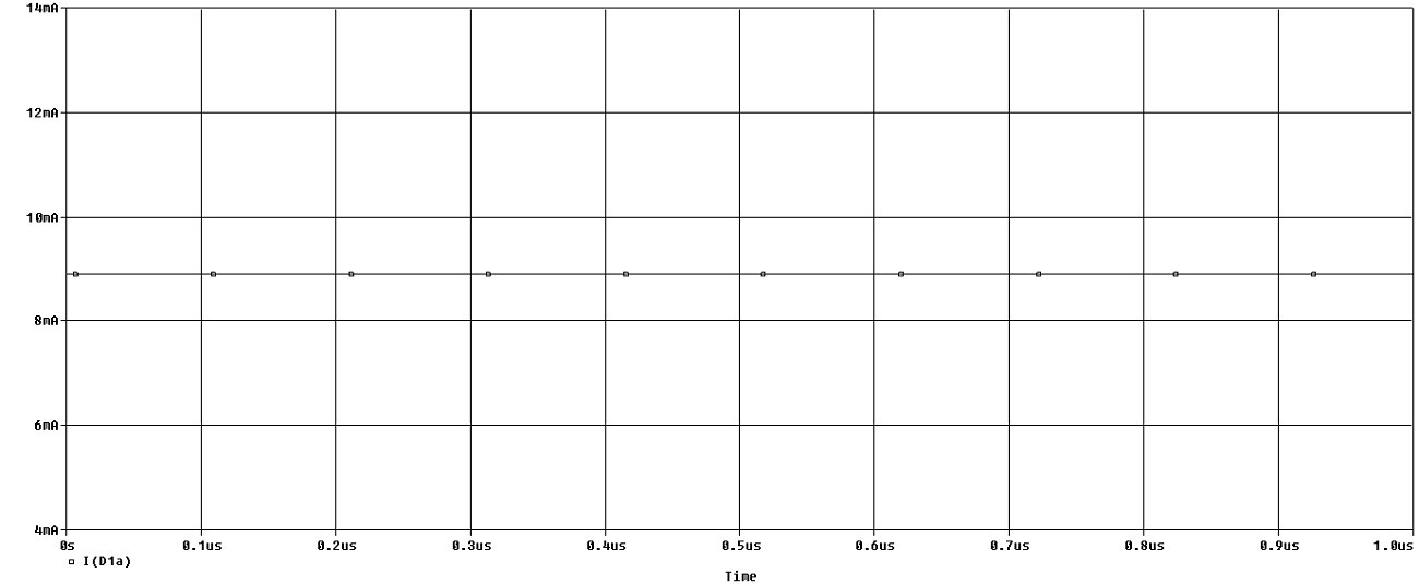
Step 2: Simulations
Simulations show a forward current of almost 15 mA as predicted in the calculations.
![]()
Step 3: Make the Circuit
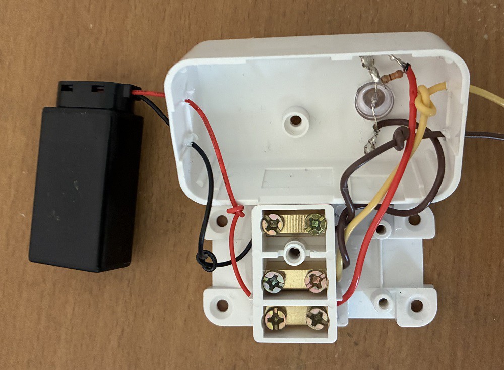
I used a junction box to connect my circuit. I had to use a soldering iron to connect the 330 ohm resistor to the LED because the junction box did not have enough connectors (this is a standard junction box from a hardware store that has three connectors for active, neutral, and earth).
![]()
Step 4: Testing
I used the circuit to test a green LED (non-blinking LED):
Conclusion
This article shows you how to design and make a simple LED tester.
-
Reflection Detecting Cars
09/06/2023 at 05:36 • 0 commentsThis article is about reflection-detecting cars with no semiconductors included apart from the LEDs.
You can read a similar article here:
https://www.instructables.com/Reflection-Detecting-Cart-With-No-Semiconductors/
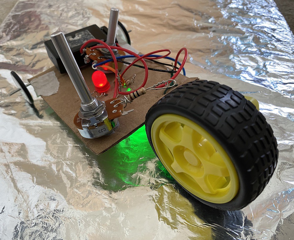
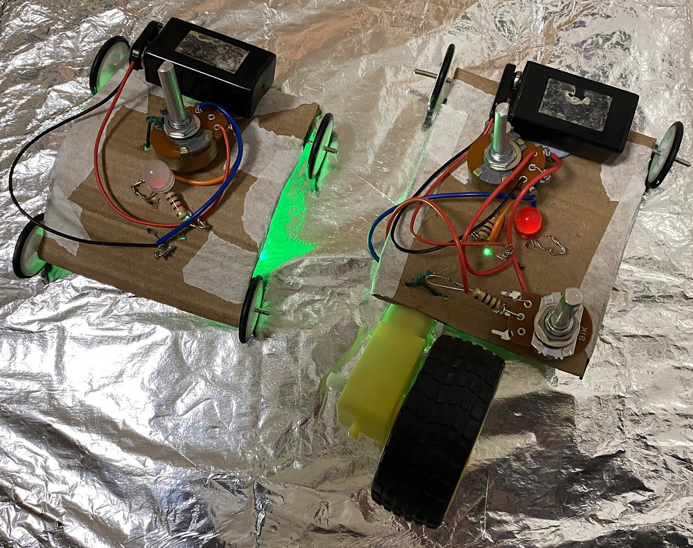
Car with motor:
![]()
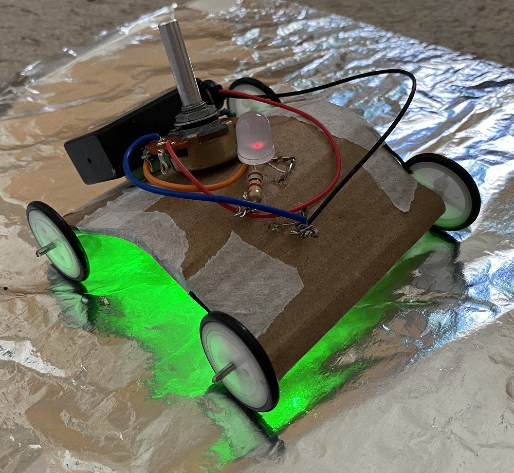
Car without motor:
![]()
The cars work on the principle of light reflected from the foil that causes the LED to turn ON and OFF. This occurs because the foil is not even and different amounts of light are entering the sensor.
You can see the toy cars working in this video:
You might think that the LED is blinking because of power surges caused by the motor gear. This is why I also made a car with no motor to prove my concept.
Step 1: Design the Circuit
I used old PSpice simulation software that does not have an LED component. I modeled the LED with three general-purpose diodes.
The more light falls onto the LDR (light-dependent resistor) the smaller is the LDR resistance. In bright sunlight, the LDR resistance can fall to about 1 kohms.
![]()
I also included the illumination LED because there is little light underneath the car. The potentiometer is used to prevent saturation of the LED.
The 1.5 V AA battery pair (providing 3 V) would have been very useful for the motor, providing the right amount of current. However, because the minimum resistance of LDR does not fall below about 1 kohm I had to use a 9 V battery instead of two 1.5 V batteries. One solution was to use a separate battery for the motor gear. However, I decided to use a 9 V battery for the motor instead and included a resistor to reduce the current. The video shows that the car was very fast because of the high 9 V battery voltage.
Calculate the maximum LED current:
IledMax = (Vs - Vled) / Rldr
= (9 V - 2 V) / 1.2 kohms
= 5.833 mA
This current is very small for the LED that needs 20 mA. One solution is to connect multiple LDRs in parallel to increase the current. However, this solution will cost a lot of money.
Step 2: Simulations
I simulated the circuit with PSpice simulation software, student edition version 9.1
The graph below shows the currents for the two LEDS and the motor.
![]()
Step 3: Make the Circuit
I made the circuit with pliers by twisting the component legs with pliers. I did not use a soldering iron.
Top of the car:
![]()
Bottom of the car:
![]()
Step 4: Attach Metal Wire Reinforcements
I reinforced the cardboard with metal wire to prevent it from bending because the piece of cardboard can bend under pressure:
![]()
You can just see the green insulated 1 mm metal wire underneath the masking tape:
![]()
Step 5: Testing
Testing showed that the cars are working but the blinking of LED is not very evident.
![]()
Bottom of the car with motor:
![]()
Bottom of the car with no motor:
![]()
Video of the car with motor:
Video of the car with no motor:
Conclusion
You can make a photosensor car with semiconductors, as explained in this link:
-
Blinking LEDs
08/28/2023 at 05:10 • 2 commentsThis article is about simple oscillators that you can build from blinking LEDs.
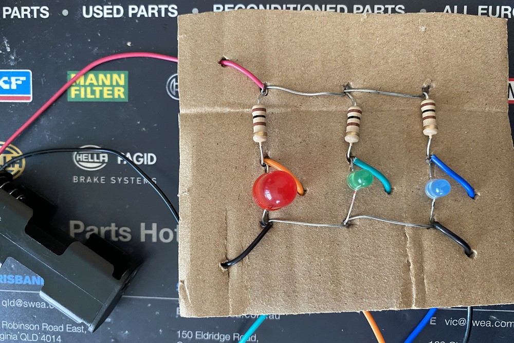
Circuit 1:
![]()
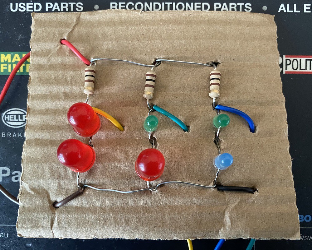
Circuit 2:
![]()
You can see the circuits working in those videos:
Circuit 1:
Circuit 2:
Those videos do not show the waveforms that the circuits are generating. You will see the waveforms in the testing section of this article.
Step 1: Design the Circuit
I have drawn the two circuits in PSpice Student Edition version 9.1.
I modelled the LED with three diodes because this old software does not have an LED component.
Circuit 1:
![]()
Maximum LED current:
Iled = (Vs - Vled) / Rled
= (3 V - 2 V) / 100 ohms
= 10 mA
Circuit 2:
![]()
Maximum LED current:
Iled = (Vs - 2*Vled) / Rled
= (5 V - 2*2V) / 100 ohms
= 10 mA
Step 2: Simulations
Simulations show a maximum current that is slightly smaller than 10 mA for both circuits because of inaccuracies in the diode model:
Circuit 1 Simulations (maximum current):
![]()
Circuit 2 Simulations (maximum current):
![]()
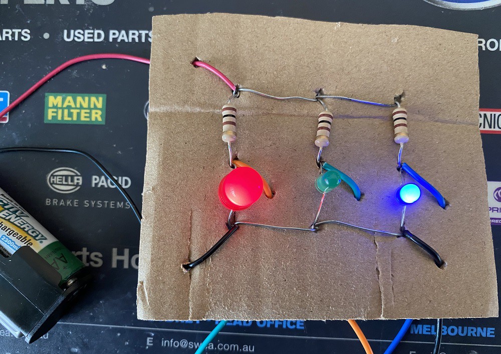
Step 3: Make the Circuit
I made the two circuits on a piece of cardboard to save money:
Circuit 1:
![]()
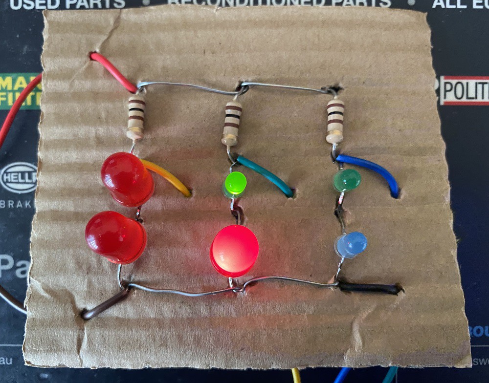
Circuit 2:
![]()
Step 4: Testing
In the photos of the circuits above, you see different colour wires connected to LED pins. Those wires are the recorded oscillator outputs.
I used the Hantek 6022BE USB Oscilloscope to record the signals:
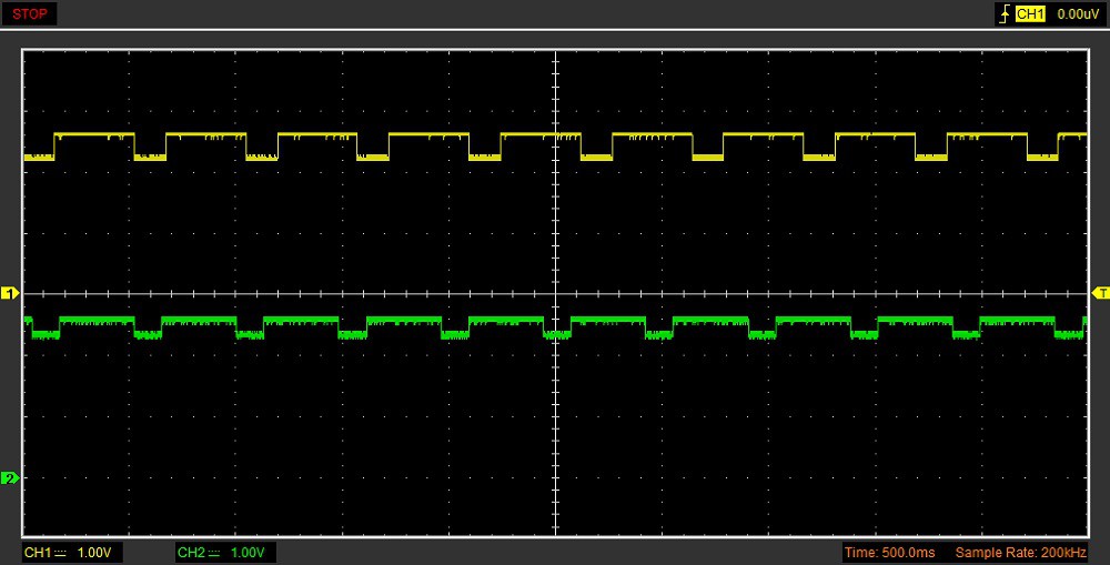
Circuit 1 (Orange and Green):
![]()
(yellow waveform - orange wire, green waveform - green wire)
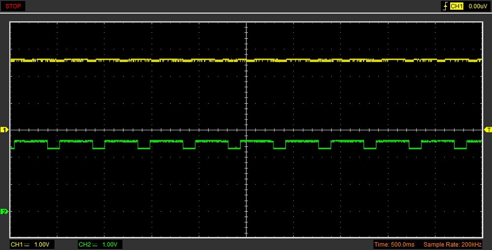
Circuit 1 (Blue and Green):
![]()
(yellow waveform - blue wire, green waveform - green wire)
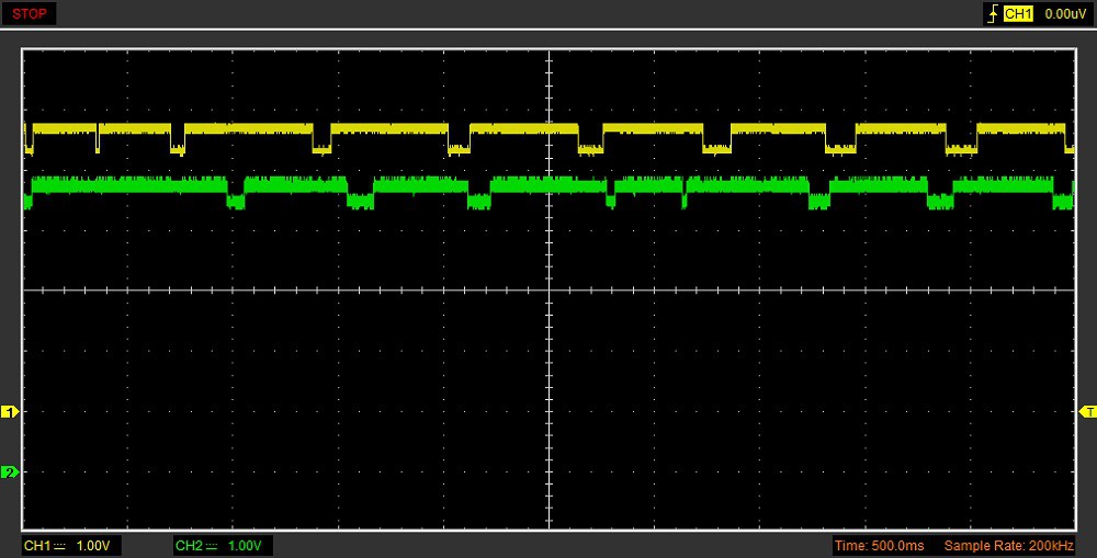
Circuit 2 (Yellow and Green):
![]()
(yellow waveform - yellow wire, green waveform - green wire)
Circuit 2 (Blue):
![]()
Testing shows that not all LEDs generate a decent square wave (or pulse width modulation) signal.
Testing showed that bigger LEDs that consume more current generate higher amplitude waveform signals.
However, the signals from blue LEDs were a lot smaller than signals from green LEDs because the two LEDs were produced by different companies, although they are the same size.
Conclusion
The circuit with three single LEDs, generated waveforms that appeared to be square wave signals. The circuit with LED pairs generated waveforms that looked like PWM (Pulse Width Modulation) signals.
You can also make oscillators with buzzers:
My Pages


Projects I Like & Follow
 Lutetium
 Gareth Coleman
 Julien
 Kevin Harrington
 M.daSilva
Publys is an open source platform for the study and processing of bioelectric signals.
 Ever
Ever Platinenmacher
 Mike
Mike Michael G
 Robert Manzke
 Beto Green
 Subir Bhaduri
 samm928
 Xavi Cano
 dave
dave Dmitry
 Tom Quartararo
 chris.coulston