-
Why Your MOSFET Keeps Failing (And How a Gate Driver Could Save It)
11/11/2025 at 04:02 • 0 comments![]()
Ever spend hours swapping MOSFETs only to have your circuit still misbehave? Overheating, mysterious ringing, and unexpected shutdowns—sounds familiar? For years, I blamed the MOSFET itself, assuming newer or “better” parts would fix everything.
Here’s the twist: the MOSFET is just the actor. The real director is the gate driver, silently orchestrating every switch, transition, and joule of energy. Without a competent driver, even the most advanced MOSFET stumbles—switching losses spike, EMI skyrockets, thermal stress mounts, and lifetime plummets.
In this Hackaday.io post, I’ll break down practical techniques, PCB layout insights, driver design tips, and field-tested solutions—all actionable, deep, and perfect for makers, hobbyists, and professional engineers alike.
The MOSFET and Its Gate Driver — The Actor and the Director
Imagine a MOSFET switching at hundreds of kHz, handling amps of current. It’s brilliant when guided well. But slow gate voltage, insufficient drive current, or a sloppy PCB layout? Performance collapses. You see high transition losses, EMI spikes, ringing, and heat buildup.
Takeaway: Designing a MOSFET driver isn’t optional—it’s designing reliability.
Driver Topologies That Matter
-
Integrated driver ICs — simple, reliable for standard modules.
-
Push-pull (totem-pole) drivers — provide sharp edges for fast switching.
-
Half-bridge drivers — essential for paired MOSFETs in motor drives and DC-DC converters.
-
Turn-off acceleration pulses — speed turn-off, but risky if misused.
6 Questions Every Hardware Hacker Must Ask
-
Is the drive current sufficient?
Slow gate charging = longer transitions = higher switching losses. Boost carefully. -
Is the gate voltage correct?
Too high = stress; too low = incomplete conduction. -
Output impedance balanced?
Low impedance stabilizes voltage; small series resistors can tune speed and reduce ringing. -
PCB layout optimized?
Switching loop area dictates EMI and ringing. Short traces, clear returns, solid ground planes. -
Thermal paths adequate?
Even the best driver fails without proper heat management. -
Damping elements in place?
Gate resistors, snubbers, and targeted damping often solve stubborn field problems.
Practical Tips You Can Apply Today
-
Use small series gate resistors to control ringing.
-
Add snubbers at high di/dt nodes.
-
Place decoupling capacitors close to switching devices.
-
Combine low-impedance drivers with small resistors for balanced performance.
-
Add thermal sensors or protection for live circuits.
Troubleshooting Workflow
-
Capture gate waveforms: rise/fall times, overshoot.
-
Verify gate resistor values and driver current capability.
-
Measure switch-node spikes to infer loop inductance.
-
Temporarily slow switching (increase gate resistance) — improvement points to parasitic issues.
-
Add damping or snubbers and reassess.
Busting Common Myths
-
“New MOSFET fixes everything.” → False. Driver design matters more.
-
“Max gate voltage is best.” → False. Overvoltage shortens life.
-
“Rds(on) tells the whole story.” → False. Dynamic parameters (Coss, Ciss, Qg) dominate switching behavior.
Final Thoughts for Hackers and Makers
Stop swapping MOSFETs blindly. Focus on gate driver optimization, PCB layout, thermal design, and damping strategies. Often, simple tweaks solve the hardest field problems—faster, cheaper, and more reliably.
💬 Share your waveforms, operating voltage/frequency, and load type, and I’ll guide you through a practical diagnostic roadmap for circuits, layout, and tuning—without recommending specific products.
SEO/Discoverability Keywords (Hackaday.io Friendly)
MOSFET troubleshooting, gate driver design, switching losses, EMI reduction, PCB layout tips, thermal management MOSFET, power electronics hacking, DC-DC converter design, motor driver circuits, MOSFET ringing issues
-
-
The Unsung Hero of Power Electronics: Why a Tiny Gate Resistor Can Make or Break Your Circuit English Version
10/30/2025 at 03:59 • 0 commentsIt was a quiet afternoon in the lab when I first realized how overlooked the humble gate resistor really is. My MOSFETs were acting wild — chaotic spikes, ringing, EMI shooting up. Drivers were solid, heatsinks hefty, yet the waveforms looked like a symphony of chaos.
Then I noticed the tiny gate resistor (Rg). A component so small, yet it held the power to turn disorder into harmony. It’s the unsung hero that controls switching rhythm, waveform integrity, and even the lifespan of your circuits.
![]()
Why Gate Resistors Matter
A MOSFET gate is deceptively simple but highly sensitive. Each switching edge delivers a surge of current. Without control, parasitic inductance and capacitance amplify chaos: ringing, overshoot, EMI, or even catastrophic failure.
Think of the gate resistor as a traffic cop at a busy intersection 🚦:
-
Limits instantaneous current — protects the MOSFET and driver
-
Controls switching speed & suppresses ringing — keeps EMI in check
-
Stabilizes logic signals — prevents floating gates and false triggers
Even tiny adjustments can convert a borderline unstable design into a rock-solid system.
![]()
Choosing the Right Rg
No one solution fits all. Options include:
-
Fixed resistors — simple, reliable
-
Adjustable / segmented resistors — ideal for tuning switching speed
-
RC networks — smooth high-frequency transitions, absorb spikes
-
Ferrite beads or EMI filters — taming high-frequency noise ⚡
![]()
How to Pick the Right Value
-
Start with driver specs — peak current & MOSFET gate charge (Qg)
-
Decide your focus — speed, reliability, or low EMI
-
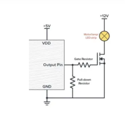
Layout matters — place Rg close to the gate pad
-
Consider asymmetry — fast turn-on, slower turn-off reduces stress
-
Add protection — RC or TVS networks for noisy/high-voltage conditions
Debugging and Optimization
Use your oscilloscope like a detective’s magnifying glass.
-
Observe Vgs, Vds, and driver signals
-
Track rise/fall times, overshoot, and ringing amplitude
-
Test under varied loads and frequencies
-
Gradually adjust Rg, logging switching loss, temperature, and EMI — tiny tweaks often yield big improvements
![]()
Common Mistakes
-
Rg too far from gate → more parasitic inductance → worse ringing
-
Missing pull-down → gate floats at startup
-
Optimizing only for speed → MOSFET burnout
Takeaway
This tiny resistor dictates your switching waveform, EMI, and system reliability. It’s not just a passive component — it’s the hidden maestro behind smooth, efficient, and durable circuits. Observe, tweak, and even the wildest MOSFETs can perform like a well-conducted orchestra.
💬 Discussion Prompt
Have you ever tuned a gate resistor and seen your waveforms go from chaotic to clean? Share your oscilloscope screenshots and tuning stories — let’s create a practical knowledge hub together! 👩🔧👨🔧 -
-
⚡ MOSFET Bidirectional Switch: Smarter Power Control for Your Circuits
10/22/2025 at 08:42 • 0 commentsEver had a seemingly fine circuit board suddenly fail—backflow currents, unexpected resets, or even fried components?
A tiny MOSFET bidirectional power switch can prevent most of these power management issues. Let’s explore how this small component wields huge influence.
![]()
1️⃣ What is a Bidirectional Switch?
A bidirectional switch allows current to be precisely controlled between positive and negative terminals.
- NMOS → controls negative side, connects to ground when ON
- PMOS → controls positive side, connects to VCC when ON
Benefits: ✅ Low ON resistance → minimal power loss ✅ High OFF resistance → excellent backflow isolation ✅ Supports high voltage & current
Illustration suggestion: simple bidirectional switch schematic + current flow arrows
2️⃣ Engineering Challenges
Designing a reliable bidirectional switch requires attention:
- Gate control signals must be precise to avoid accidental conduction
- ON/OFF resistance must be optimized
- MOSFET voltage/current ratings must meet design specs
Pro Tips:
- Carefully select NMOS/PMOS for matching voltage and current
- Optimize gate waveform to reduce switching loss
- Mind parasitic resistance and capacitance for fast response
Illustration suggestion: waveform diagram + ON/OFF comparison
![]()
3️⃣ Practical Applications
Bidirectional switches are essential for:
- Advanced power management modules
- Mobile and portable electronics
- Smart home and wearable devices
Proper NMOS/PMOS control enables efficient, low-loss, and reliable power switching.
Illustration suggestion: schematic showing smart home module or portable electronics with MOSFET annotation
![]()
4️⃣ Engineering Philosophy
Tiny components can decide the stability and safety of your circuits.
Mastering bidirectional switches improves technical skills and helps avoid pitfalls in power system design.
Social Hooks for Sharing
- “Small component, big impact—complete guide to MOSFET bidirectional switches”
- “Make your circuits smarter: master bidirectional switch design ⚡”
This user joined on 06/26/2024.
My Pages


Things I've Built
https://www.vbsemi.com/
 Lutetium
 Xylitol
 Dessislav Gouzgounov
 Flavio
 Curt White
 lion mclionhead
 Nick Thatcher
 Hugo Melder
 gamaral
 mircemk
 Vinch
Vinch Adam Fabio
 Voja Antonic
 Kim Salmi
 Brijesh Sondarva
 Implemented Robotics
 Mike Szczys
 TEC.IST