-
The first batch of 200 has gone out!
09/29/2025 at 01:35 • 0 commentsWell, almost. We're shipping 5-6 PiDP-1s per day at the moment, working our way through the waitlist of daring early adopters. Thank you, all of you! We really, really appreciate the confidence.
Now, we're waiting for parts to make the next 300. Over on the PiDP-1 Google Group, the fun has started. So far: a new disassembler, a new cross-assembler, a Forth and a Lisp (in Forth amazingly) have been written, plus a toolbox to inspect and convert paper tape images.
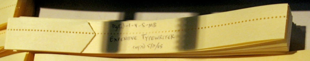
We've gotten Lisp to work, and the standard development suite of Expensive Typewriter (oops, Symbolic Tape Editor in DEC's own words), MACRO and DDT.
![]()
And work is underway to hook up modern I2C peripherals.
We're having fun! You do not need to have the PiDP-1 hardware to join in, the virtual front panel version works just fine on a Pi, Linux laptop or even Windows WSL2: PiDP-1 Github repository. Please come and join the fun. Plenty of software archaeology left to do (who will bring up FORTRAN?)
![]()
-
Making a pretty case out of PCB panels
08/08/2025 at 06:28 • 0 commentsI think this little video is interesting for more than just vintage computer fans: it shows how we made a very complex-shaped case out of just PCB panels. It took a lot of experimentation (see earlier log posts) but it works extremely well. The end result is a case that is so strong, you can drop it from 5 feet on a concrete floor. We tested that, although not on purpose.
Here is the video:
...And look further down in the log posts for technical details. Perfecting this trick saved us a small fortune (which the budget actually did not allow for) compared to other case-building techniques like injection molding (yuck).
Meanwhile, we're busy packing up the first 200 kits :-) -
It's done! We're making PiDP-1 kits
08/06/2025 at 05:06 • 0 commentsIt took much longer than expected, because of recurring logistical trouble. There's a lot of parts in the PiDP-1, and that made it a real logistical nightmare. Custom-designed aluminum profiles were one challenge.
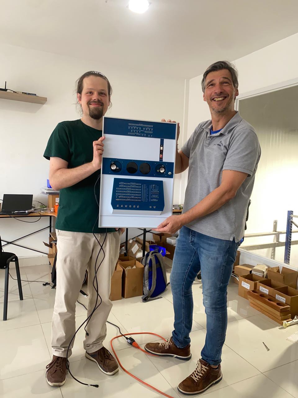
But: It's done. We started making PiDP-1 kits today!
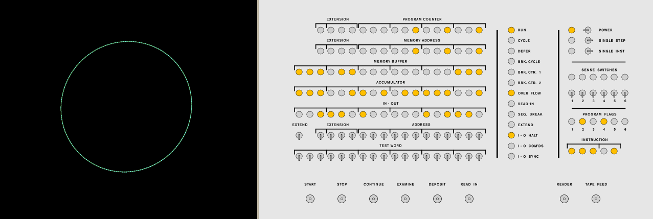
Here is the smaller of the two variants we designed, the PiDP-1 Console, Does it look like a retro games console? That is the plan. We're starting to write some new games for the machine. The type 30 vector display is very fun to code for.
![]()
So, the hardware development has come to an end. Now comes the real fun: reviving the 1959 PDP-1 with a hopefully active community of users and programmers. For the latter, we're writing a book. "Democoding on the PDP-1: A gentle introduction". Because this was the original democoders' machine, and if it is up to us, it will be again.
-
Into production! And book publishing?
06/22/2025 at 15:59 • 1 commentAn update - all parts to make 200 PiDP-1 kits have been ordered. We were forced to use sea container shipping to keep costs under control. Things like the custom aluminum frame are heavy - but so is shipping all the PCB parts for 200 kits: the case is constructed from FR4 PCB material, giving a nice chunky weight to our little replica - but alas, shipping spoils the fun a little bit :-)
We're now focusing on polishing up the software, and on writing a PDP-1 programming manual. Ambitiously called "Democoding for the PDP-1: A Gentle Introduction". Four of us started making some appealing graphics demos with fully commented step by step source code. This will be fun!
![]()
-
Finished the first test batch of 5 machines
04/05/2025 at 18:03 • 6 commentsIn other words, we increased the number of PDP-1s ever produced by 10% in two days :-)
![]()
Lots of polishing up still two do. We're hiding from the world for two weeks to get it all done. Probably <i>almost</i> all done. <i>Mostly done.</i>
-
Spacewar controllers and Feature Creep
03/15/2025 at 01:04 • 0 commentsSo, we want to make the PiDP-1 a very affordable kit to make. Because, the more affordable the more chance that it will find its way to young coders who want to try their hand at PDP-1 programming!
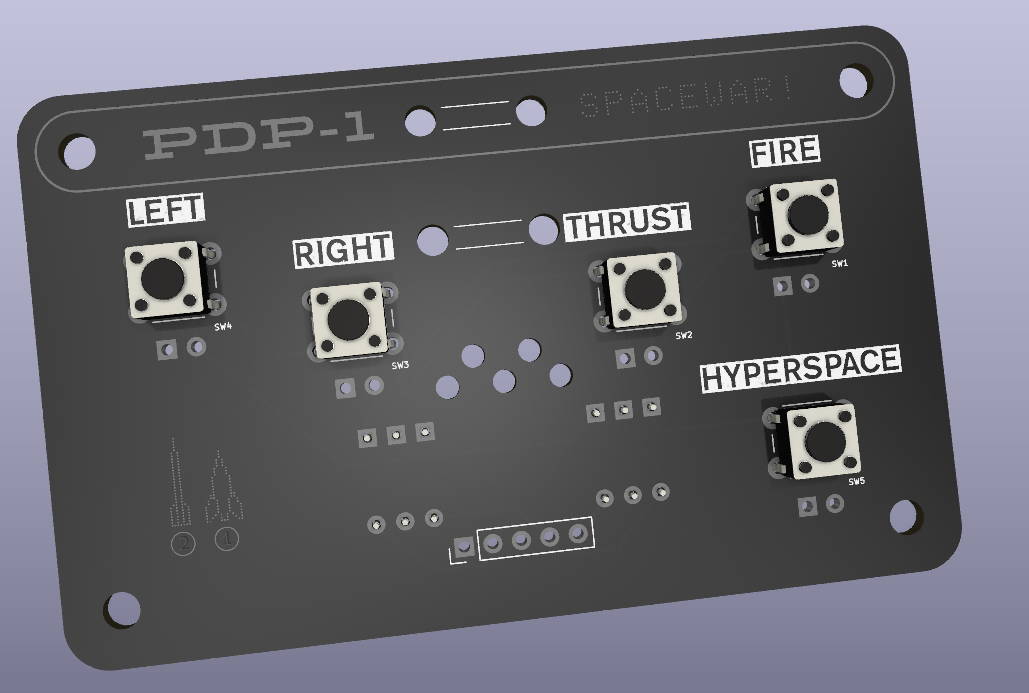
But we're battling feature creep, we'll just have to add two spacewar controllers. The idea is to make it them tiny, low-cost PCBs that will do the job on their own, but at the same time, can be the PCB inside a proper custom-made wooden spacewar control box. As the original ones were all quite visibly one-off jobs too, a proper spacewar controller must look - artisanal.
But for those who do not like to tinker, they can use the PCB as-is:
![]()
As we had 36 extra IOs for lights or switches, we did spend the whole day thinking of other exotica to add. For instance, the three PDP-1s that made it onto Arpanet had extra button boxes - the time-sharing operating system used them to hook up multiple Teletypes.
But we decided against such things, they can all be done in software and the kit is already a package of 15 PCBs as it stands. And though PCBs are cheap, it does add up.
-
The PDP-1 and Arpanet
03/13/2025 at 13:22 • 0 commentsWe spent the last four days investigating how we can bring our PiDP-1 on Arpanet. Yes, really. Because (1) there is some major history there, and (2) there's a major new project from Lars Brinkhoff where this would be significant Icing On The Cake.
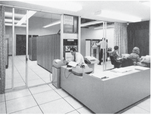
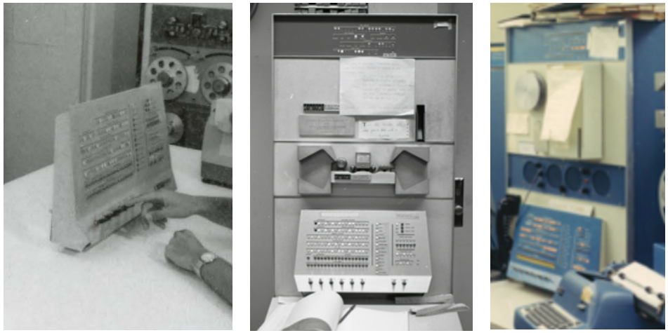
The history: so Arpanet consisted of IMP routers. Not very well-known is that the software for the IMPs was developed with the help of a PDP-1, at BBN by a small team called The IMP Guys. Actually, in the first-ever instance of remote software updates, the PDP-1 sent over-the-net software updates to all the IMP routers in the field. The PDP-1 also acted as the watchdog for Arpanet stability, constantly chatting to the IMPS in the field.
And as it happened, we were brought in touch with one of the actual IMP Guys at BBN - who did the coding. We found large parts of the PDP-1D time-sharing system (alas, in PDF format) and lots of technical memos from the IMP Guys. So - we now have to think about how impossible it would be, exactly, to get that all going again on the PiDP-1.
![]()
Arpanet in 1973, with BBN and its PDP-1 in the top-right section
The major new project: Lars has brought up the simulator of the IMP hardware, running the original software, got the Arpanet code running on PDP-10s with ITS (so we 'have MIT up on Arpanet) and with WAITs (so we 'have Stanford up on Arpanet'). As well as PDP-11s running unix v6. Although, that's not quite up yet. Amazingly, he also wrote a Network Control Program for Linux - so any Linux box now connects to real or simulated IMPs and go out on Arpanet.
So - imagine, if we can get the PDP-1 at BBN online too, we'd have a pretty full reconstruction of Arpanet circa 1973. But reality now sets in - will we really be able to get the PDP-1's Network Control Program back? Large chunks outside the OS are missing and will have to be rewritten.
![]()
The PDP-1 at BBN, just before the Era of Arpanet
--> this is a call for help! If you have any old code, documents or papertapes relating to the PDP-1 at BBN, Stanford or USC, please, please let us know.
-
Making a case out of PCB panels
03/02/2025 at 17:39 • 0 commentsSome more information about how we created the PCB panels that soldered together, form the PiDP-1's case (Cases, we have two variants...).
In the Files section, we've placed a Kicad PCB design file which turned out to work well; maybe they are interesting for other projects.
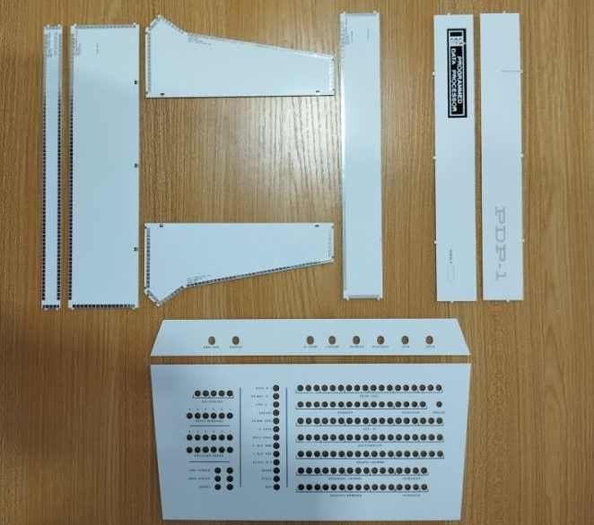
Here is the PCB set that makes up the stand-alone console version of the PiDP-1. Two sides, a top and bottom panel, and a thin panel that sits at 45 degrees at the front-bottom of the case:
![]()
We went through a couple of months experimenting with the solder pads, the sizing of the tongue-and-groove pairs that clip one panel into another, and the fitting of the removable back panels - which are the two strips at the top right. We don't want these to be soldered in permanently, so they just are clicked in.
The '3D' solder pads need to be strong, and placed as close to the panel edge as PCB manufacturers allow. Make them too big, and a simple soldering iron will not provide enough heat to make the 3D solder connections. Make them too small, and the do not stick to the PCB well enough.
Also, the tongue-and-groove pairs that help ensure a perfect alignment required some experimentation. First though - yes, they also provide some extra strength as well, but are not really needed for that purpose as it turns out. Anyway - the problem with these pairs is their precise dimensioning. When the PCB manufacturer routes out the PCB's outline, the router bit does not always have the same diameter. We've done plenty of prototype tests by now so conclude that a 0.1mm of extra space is needed around such features (the tongue is 0.1mm smaller on either side than the groove it fits in) to give (a) a good fit and (b) will not cause trouble in extreme cases of manufacturer tolerance.
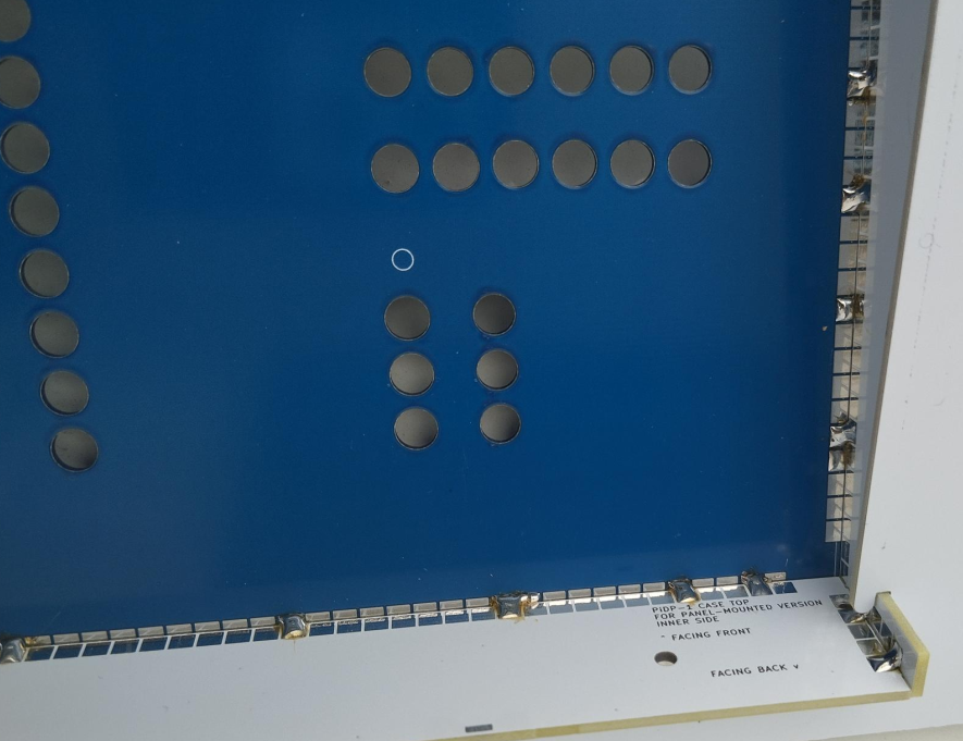
![]()
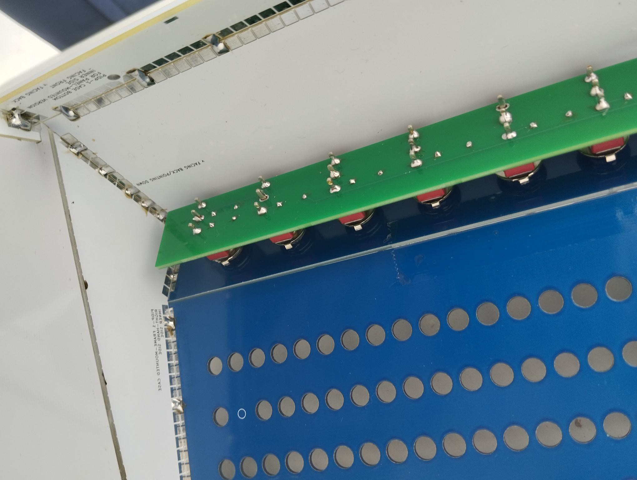
Here is the inside of the case (or frame) used for the rack-mounted PiDP-1, showing the solder points. It takes less than two seconds to do each solder spot, and we found that doing the solder spots every few cm apart already gives all the strength you want. This will hold even if you drop the case on a concrete floor - an unintended experiment.
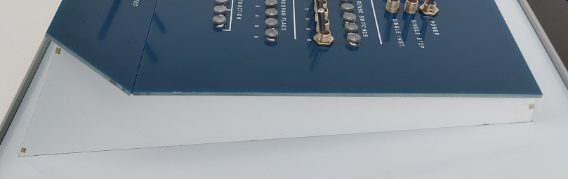
We feel the end result is easy to build, but also looks very good from the outside. Here is a detailed shot of the base of a console PiDP-1:
![]()
You can certainly leave out most of tongue-and-groove features. The soldering alone makes the case strong enough. But it does make it a lot easier to construct the case, without having to worry about alignment issues.
Perhaps more detail than anyone wants, but we spent quite some time experimenting and if you consider PCB cases for other projects, maybe the Kicad file we put in the Files section will be of use.
-
Problems and solutions
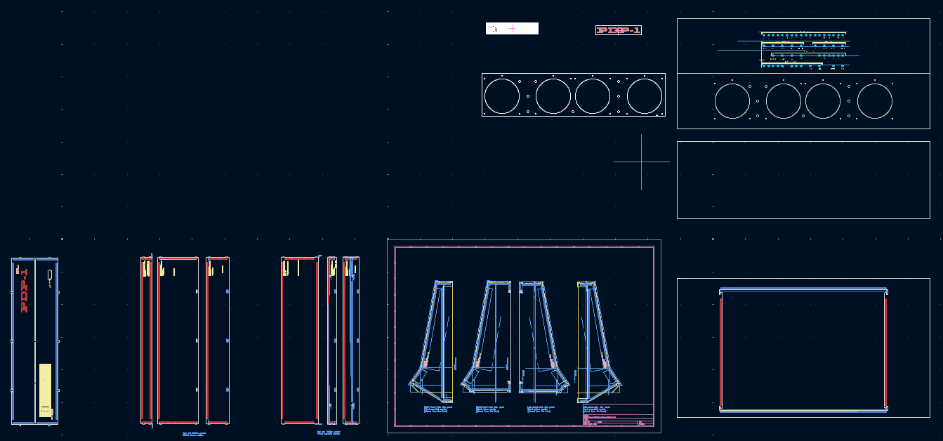
03/02/2025 at 10:07 • 0 commentsThe PDP-1 has a somewhat complex shape, and we did not want to resort to either 3D printing or making molds for the case. So I experimented with making a case from PCB panels, inspired by Bobricius's projects.
In the end, these became the parts for the two case variants (stand-alone console and rack-mounted):
![]()
In all, 19 pieces of PCB just for constructing the cases. But with the current low prices for PCBs, that is still much more affordable than any other approach we tried.
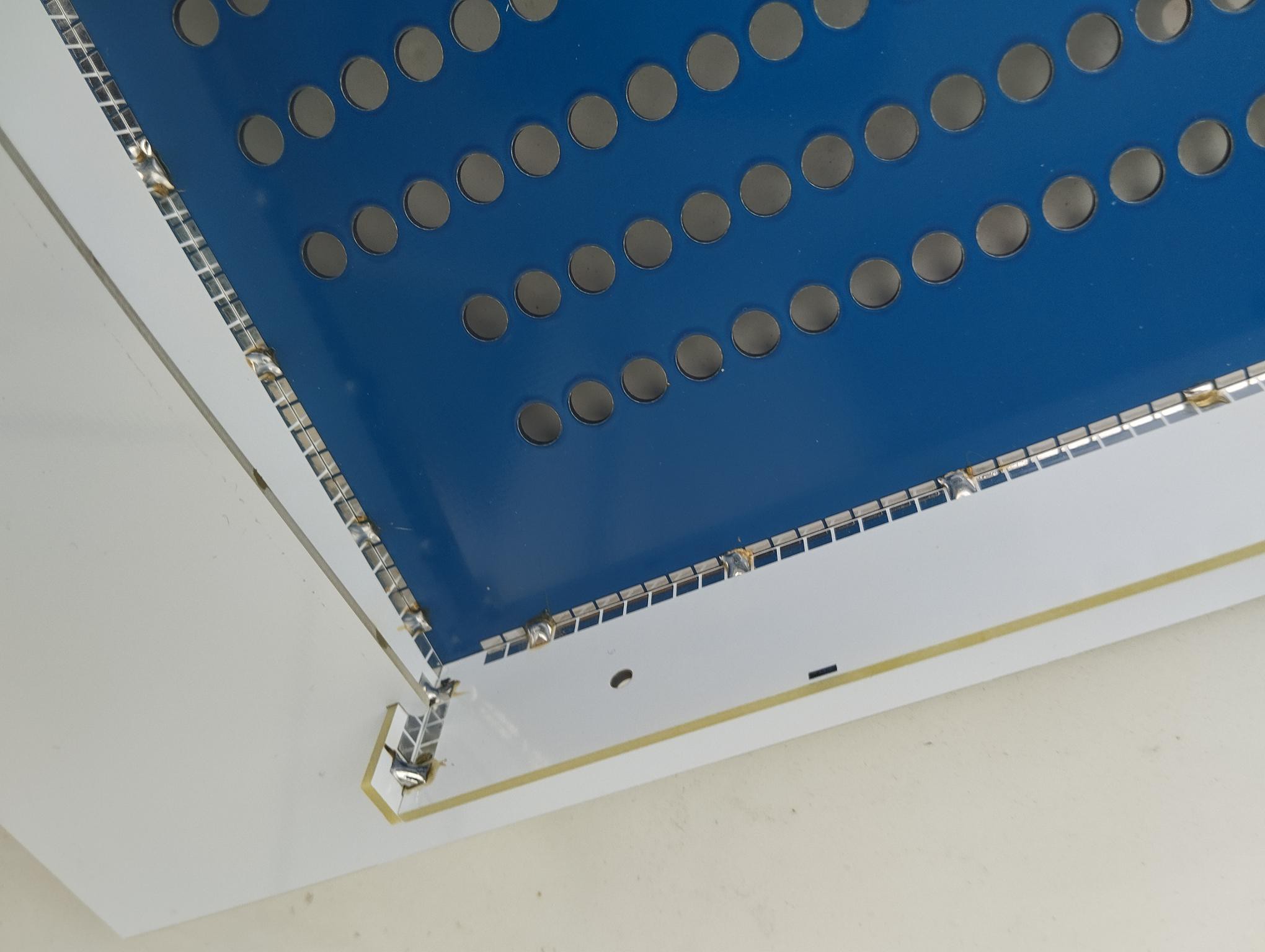
Constructing a 3D object from PCBs turns out to be very simple, and very strong as well. Here is a detailed shot of the case's inside:
![]()
As it turns out, a couple of solder points on each edge make for a very sturdy construction. You can drop it on a concrete floor without anything bad happening! On the outside, I think it looks pretty nice:
![]()
Side of rack-mounted version
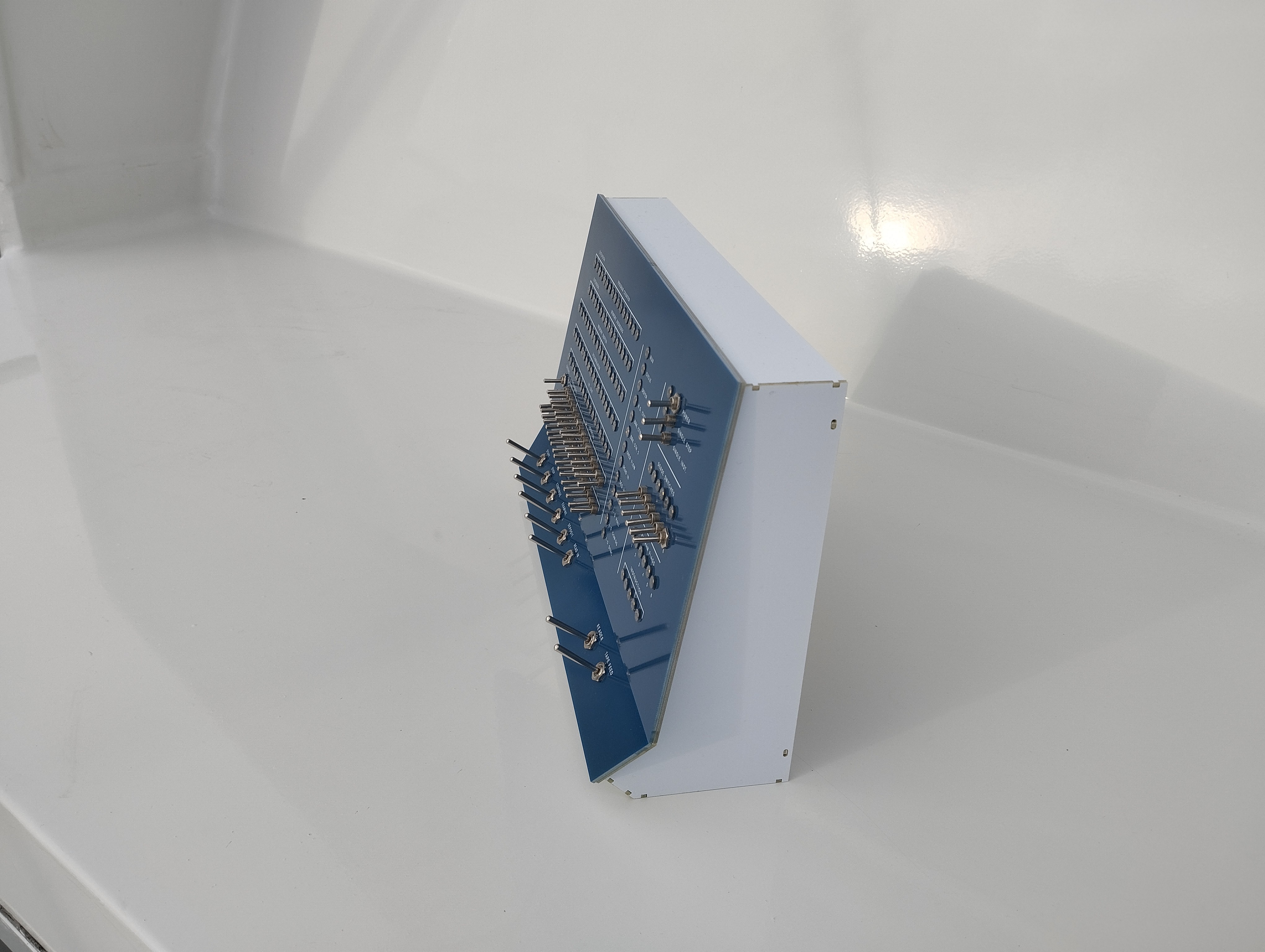
![]()
Side of stand-alone console version
Another challenge was the mounting of the front panel onto the case. The original has no visible bolts or clamps on its front. Here, too, the solution was to solder the pack of the front panel to the sides of the case. That also allows a very precise fitting of the parts.
![]()
-
Choosing a PDP-1
03/01/2025 at 22:44 • 0 commentsThere seems to be a bug that hides the picture in the previous post, this one:
![]()