-
Implementation Scheme for I²C Operation during Linux 4.9 System Startup on T507 Platform
6 days ago • 0 comments1. Product Configuration
Product: T507
Hardware Configuration: v1.1
Software Configuration: Linux 4.9
2. Requirement Description
- The SoM needs to send an initialization sequence viaI²C.
- The registers of the temperature sensor need to be configured viaI²C.
3. Specific Implementation
- U-Boot Phase
In the U - Boot phase, it can be added to the board - levelinitialization file.
In the ft_board_setup function, there is some content for audio chipinitialization.
Specific Steps:
- Bus Initialization
① First, the pin functions need to be set.
Enable the bus.
② Switch the bus.
After switching the bus, all subsequent read and write operationswill be performed on this bus.
Suppose there are three I²C buses, numbered 3, 4, and 5, and theirnumbers in the U - Boot phase are 0, 1, and 2 respectively.
③ Perform i2c read/write operation according to chip timing.
④ The encapsulated functions of the system can also be used.
Specific Operations:
- Kernel Phase:
If it is just simple read and write operations, it does not need torely on the device tree.
Directly obtain the i2c adapter information in the entry function.The implementation of the write function is as follows.
Implementation of Writing a Function
static s32 aim955_i2c_write(struct i2c_adapter *client, unsigned short devID, unsigned char regadr, unsigned char regVal) {
struct i2c_msg msg;
s32 ret = -1;
s32 retries = 0;
static unsigned char cmdBuf[4];
memset(cmdBuf, 0x00, 4);
cmdBuf[0x00] = regadr;
cmdBuf[0x01] = regVal;
msg.flags = !I2C_M_RD;
msg.addr  = devID;
msg.len   = 0x02;
msg.buf   = cmdBuf;
while(retries < 5) {
ret = i2c_transfer(client, &&msg, 1);
if (ret == 1) {
break;
} else {
retries++;
}
}
if((retries >= 5)) {
pr_err("write AIM error device ID %d regaddr = %d value = %d\n", devID, regadr, regVal);
}
return ret;
}
Examples:
aim955_i2c_write(client, 0x0C, 0x14, 0x10);
The parameter contains the bus information device address registeraddress register value.
11-14: Initialize the msg structure, fill in flag bits, deviceaddress, and register information
17-22: Send msg information through i2c_transfer function
Driver Examples:
#include <linux/module.h>
#include <linux/i2c.h>
#include <linux/init.h>
#include <linux/kernel.h>
#include <linux/delay.h>
#define DEVICE_ADDRESS 0x5d
static struct i2c_board_info __initdata my_i2c_device = {
I2C_BOARD_INFO("my_i2c_device", DEVICE_ADDRESS),
};
static s32 aim955_i2c_write(struct i2c_adapter *client, unsigned
short devID, unsigned char regadr, unsigned char regVal) {
struct i2c_msg msg;
s32 ret = -1;
s32 retries = 0;
static unsigned char cmdBuf[4];
memset(cmdBuf, 0x00, 4);
cmdBuf[0x00] = regadr;
cmdBuf[0x01] = regVal;
msg.flags = !I2C_M_RD;
msg.addr = devID;
msg.len = 0x02;
msg.buf = cmdBuf;
while(retries < 5) {
ret = i2c_transfer(client, &msg, 1);
if (ret == 1) {
break;
} else {
retries++;
}
}
if((retries >= 5)) {
pr_err("write AIM error device ID %d regaddr = %d value = %d\n",
devID, regadr, regVal);
}
return ret;
}
static s32 aim955_i2c_read(struct i2c_adapter *client, unsigned short
devID, unsigned char regadr, unsigned char *regVal) {
struct i2c_msg msgs[2];
s32 ret=-1;
s32 retries = 0;
static unsigned char readAddr[4];
memset(readAddr, 0x00, 4);
readAddr[0] = regadr;
msgs[0].flags = !I2C_M_RD;
msgs[0].addr = devID;
msgs[0].len = 1;
msgs[0].buf = readAddr;
msgs[1].flags = I2C_M_RD;
msgs[1].addr = devID;
msgs[1].len = 1;
msgs[1].buf = regVal;
while(retries < 5) {
ret = i2c_transfer(client, msgs, 2);
if(ret == 2) {
break;
} else {
retries++;
}
}
if((retries >= 5)) {
pr_err("read AIM error device ID %d regaddr = %d error!\n", devID,
regadr);
}
return ret;
}
static void aim955_devInit(struct i2c_adapter *client) {
unsigned char data_rec=0;
int iloop = 0x00;
//Each step of cgc, 955 configuration
aim955_i2c_write(client, 0x0C, 0x01, 0x02);
mdelay(4);
aim955_i2c_write(client, 0x0C, 0x14, 0x10);
mdelay(4);
aim955_i2c_write(client, 0x0C, 0x87, 0x02);
mdelay(4);
aim955_i2c_write(client,...
Read more » -
Practical Guide: Connect and Configure an SPI Screen on the OK3568 Embedded Platform
11/14/2025 at 02:52 • 0 commentsThis article provides a detailed introduction on connecting and configuring an SPI screen in the Linux system, covering hardware wiring methods, steps for modifying the device tree, and driver adaptation techniques.
With the adaptation solution provided in this tutorial, the ST7735S screen can be quickly integrated with the Forlinx OK3568 development board, creating a cost - effective display solution for applications such as industrial control and portable devices.
If further expansion of functions is needed (such as touch control and backlight adjustment), additional development can be conducted based on this.
1. RK3568-spi Adaptation to 1.8-inch TFT Color Screen
Driver chip: : ST7735S
Resolution: 128×160, supporting 260,000 colors and 65K colors (16 - bit RGB565 format)
Interface Type: 4 - wire SPI (including CS/DC/RES/SCL/SDA pins), with independent backlight BL control
Operating Voltage: 3.3V (VCC pin, do not connect to 5V)
Communication Rate: Supports a maximum SPI clock of 50MHz
2. Hardware Connection
The connection relationship between the screen pins and the OK3568 must be strictly corresponding to ensure normal SPI communication and GPIO control.
The connection table is as follows:
Screen Pin Connected to OK3568 Function Description Notes VCC 3.3V power supply Core operating voltage of the screen Must be connected to 3.3V! Connecting to 5V will burn the chip. GND GND Power supply common ground Must be reliably grounded; otherwise, the display will be abnormal. BL 3.3V power supply Screen backlight control When not controlled by software, connect to 3.3V for constant lighting. CS spi0_cs0 SPI chip-select pin Selects the SPI slave device when at low level. DC GPIO3_A2 Data/command control pin Transmits data at high level and commands at low level. RES GPIO3_B3 Screen reset pin Pull low for reset during power-on and then pull high after completion. SCL spi0_clk SPI clock pin Provides a synchronous clock, up to 50MHz. SDA spi0_mosi SPI master-out slave-in pin Transmits screen commands and display data. 3. Device Tree Modification
diff --git a/arch/arm64/boot/dts/rockchip/OK3568-C-common.dtsi b/arch/arm64/boot/dts/rockchip/OK3568-C-common.dtsi
index 31ffd6024..2274b26ec 100644
--- a/arch/arm64/boot/dts/rockchip/OK3568-C-common.dtsi
+++ b/arch/arm64/boot/dts/rockchip/OK3568-C-common.dtsi
@@ -673,7 +673,7 @@ 	rx_delay = <0x00>;  	phy-handle = <&rgmii_phy1>;
-	status = "okay";
+	status = "disabled";     // Turn off the network port function, and the reset pin of &gmac1 conflicts with the pin of spi0 DC };  &mdio0 {
@@ -1813,12 +1813,15 @@ 	pinctrl-names = "default", "high_speed"; 	pinctrl-0 = <&spi0m1_cs0 &spi0m1_pins>; 	pinctrl-1 = <&spi0m1_cs0 &spi0m1_pins_hs>;
-	status = "disabled";
+	status = "okay";  	spi@0 {
-		compatible = "rockchip,spidev";
+		compatible = "sitronix,st7735r"; 		reg = <0>;
+		dc-gpios =  <&gpio3 RK_PA2 GPIO_ACTIVE_HIGH>;
+		reset-gpios = <&gpio3 RK_PB3 GPIO_ACTIVE_HIGH>; 		spi-max-frequency = <50000000>;
+		rotation = <0>; 	}; };
4. Kernel Driver Enable
CONFIG_FB_TFT=y
CONFIG_FB_TFT_ST7735R=y
5. driver fb_st7735r.c Modification
diff --git a/drivers/staging/fbtft/fb_st7735r.c b/drivers/staging/fbtft/fb_st7735r.c
index 9670a8989..e13625cc7 100644
--- a/drivers/staging/fbtft/fb_st7735r.c
+++ b/drivers/staging/fbtft/fb_st7735r.c
@@ -18,73 +18,49 @@  static const s16 default_init_sequence[] = { 	-1, MIPI_DCS_SOFT_RESET,
-	-2, 150,                               /* delay */
+	-2, 10,  	-1, MIPI_DCS_EXIT_SLEEP_MODE,
-	-2, 500,                               /* delay */
+	-2, 120, -	/* FRMCTR1 - frame rate control: normal mode
-	 * frame rate = fosc / (1 x 2 + 40) * (LINE + 2C + 2D)
-	 */
-	-1, 0xB1, 0x01, 0x2C, 0x2D,
+	-1, 0x11,
+	-2, 120, -	/* FRMCTR2 - frame rate control: idle mode
-	 * frame rate = fosc / (1 x 2 + 40) * (LINE + 2C + 2D)
-	 */
+	-1, 0xB1, 0x01, 0x2C, 0x2D, 	-1, 0xB2, 0x01, 0x2C, 0x2D,
-
-	/* FRMCTR3 - frame rate control - partial mode
-	 * dot inversion mode, line inversion mode
-	 */ 	-1, 0xB3, 0x01, 0x2C, 0x2D, 0x01, 0x2C, 0x2D, -	/*...
Read more » -
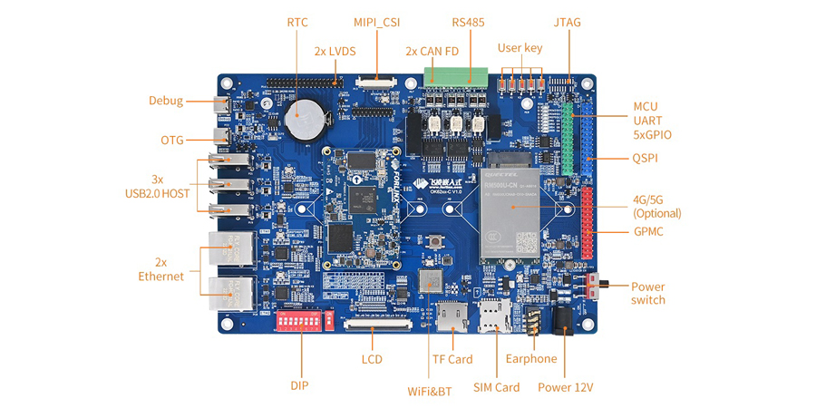
Common Interface Problems and Troubleshooting Ideas for AM62x Development Boards (2)
11/11/2025 at 02:24 • 0 commentsThe AM62x processor from Texas Instruments (TI) is a new-generation, high-performance, and low-power processor widely utilized in industrial control, human-machine interaction, and edge computing. Common issues encountered in the development of the OK62xx-C development board have been summarized, drawing significant interest from many friends.
This article lists systematic troubleshooting ideas and solutions for various interface problems that may arise during the development process.
![AM62x Development Boards]()
1. LVDS Problem
(1) Check whether the output mode of the LVDS display is consistent with the screen (VESA and JEIDA);
(2) Confirm whether the 100Ω resistors of each differential signal of the LVDS screen are soldered;
(3) Please incorporate a soft-start circuit for the LVDS power supply. Verify that the resistor at R247 is present to ensure Q3 turns on gradually, preventing the screen from pulling down VDD_5V;
(4) Measure whether the clock and data output are normal.
2. ENET Problem
(1) Confirm that the communication interface between the PHY chip and the MAC is consistent and that equal-length processing has been performed;
(2) Verify if the MDIO bus is properly pulled up and that the waveform appears normal; also, avoid splitting the MDIO wiring;
(3) Confirm whether the precision resistors meet the requirements;
(4) If the speed does not meet the requirements, check if each power supply and the reference ground are functioning properly;
(5) Detect whether the center tap of the network transformer is correct;
(6) Verify that the addresses of different PHY chips on the same bus do not conflict and are consistent with the software settings;
(7) Verify if the MDI data lines have been processed to equal lengths and if the impedance meets the specified requirements.
3. CAN Problem
(1) When there are multiple devices on the CAN bus, confirm whether there are 120Ω matching resistors at both ends of the devices;
(2) If the CAN devices cannot communicate, you can try to connect the reference grounds of the CAN devices to reduce common - mode interference.
4. UART Problem
(1) The serial port transceiver signals need to be cross - connected;
(2) Confirm whether the serial port tool configuration is correct, such as the baud rate.
(3) Measure whether the data output is normal.
5. RS485 Problem
(1) When there are multiple devices on the 485 bus, confirm whether there are 120Ω matching resistors at both ends of the devices;
(2) If the 485 devices cannot communicate, try to connect the reference grounds of the 485 devices to reduce common - mode interference;
(3) Since RS485 is a half - duplex transmission, some 485 chips require transceiver control signals. Confirm whether the chip driver has been added.
6. Audio Problem
(1) If the system cannot detect the audio chip, check whether the I2C bus communication is normal;
(2) If the chip can be mounted normally but there is no sound output, first check whether the I2S data waveform is output normally, and then check whether the audio output is normal.
7. PCIe Problem
(1) Confirm whether the PCIe device and the CPU use the same source clock and whether the frequency is correct;
(2) Detect whether there is an AC coupling capacitor for the PCIe transmission signal;
(3) Generally, an AC coupling capacitor has been added to the transmission signal at the PCIe device end, so there is no need to add another coupling capacitor at the receiving end.
8. GPIO Problem
When selecting a GPIO, confirm whether the signal is a Boot startup item pin. If so, do not use a pull-up or pull-down circuit when powering on, or a buffer chip needs to be added.
 Lutetium
 Rui Santos
 Thane Hunt
 Max.K
Max.K Michiel Spithoven
 Radu Motisan
 dev-lab
 Stephane
 CNLohr
 1BarConnection
 Xylitol
 Chris Gervang
 Alex M Sunny
 AVR
AVR Makerfabs
 Adrian Prinz
 Holotype Robotics