 Michael
This is an attempt to build a full-fledged game console, i.e. with multiple games, sound, multiple buttons - all that using one of the cheapest and lowest-end 8-bit MCU currently on the market. Thus, ATTiny10 is my MCU of choice for this project. Although, there are even cheaper and lower-spec MCUs out there, ATTiny10 seems to be minimally viable for this purpose.
Current progress
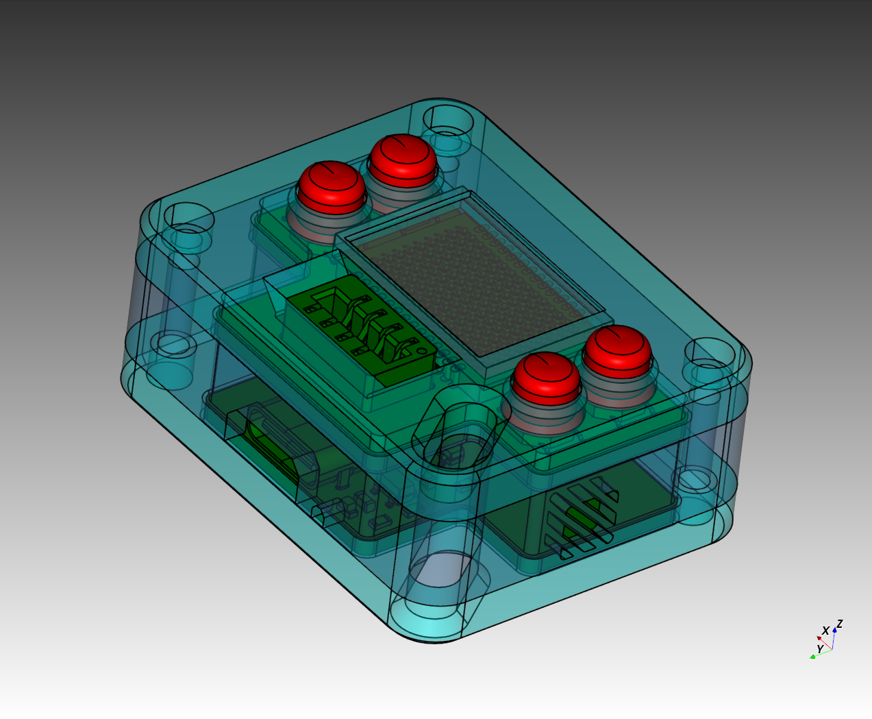
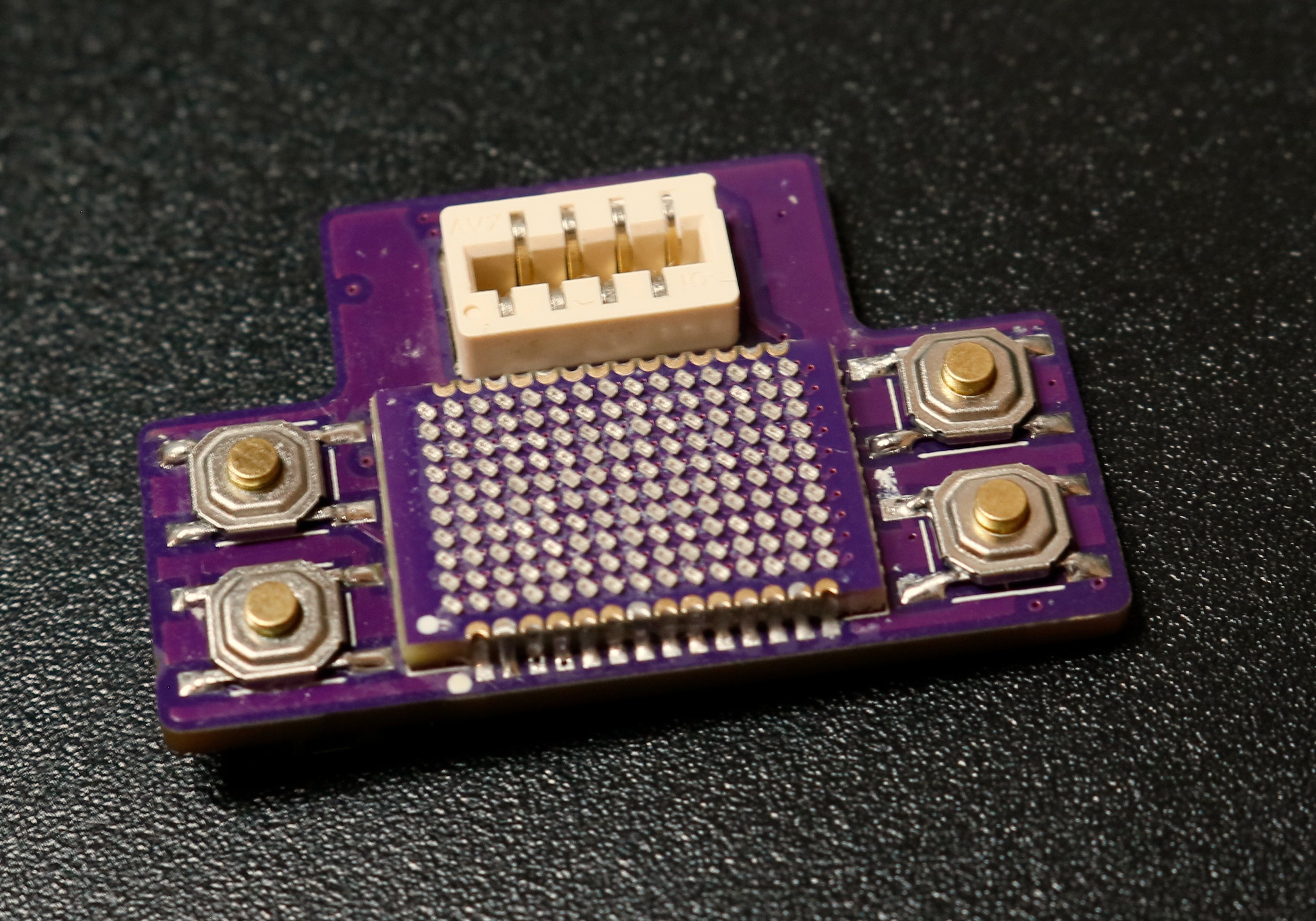
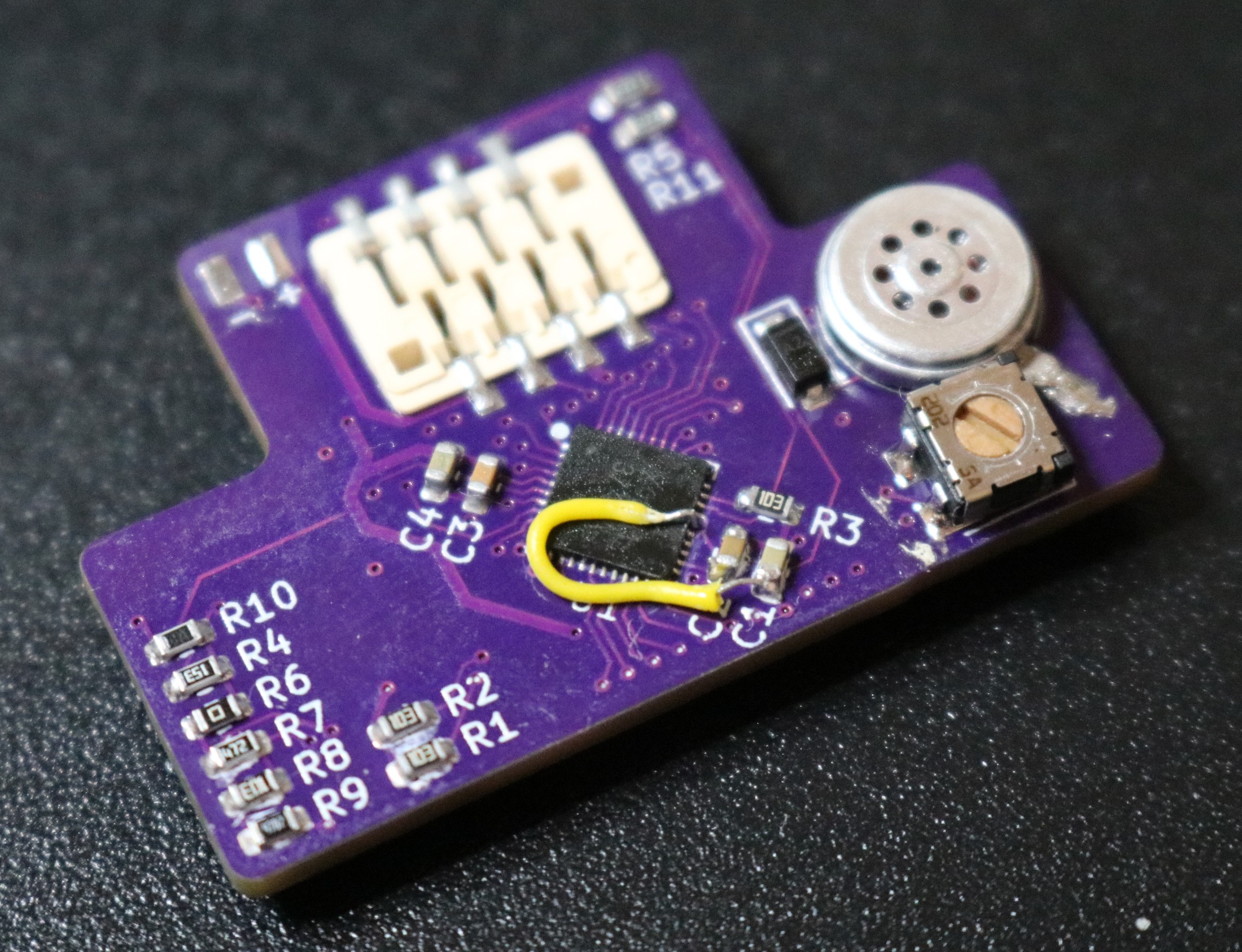
First version of the baseboard and cartridge PCBs were designed and ordered. The first PCB prototype was assembled.
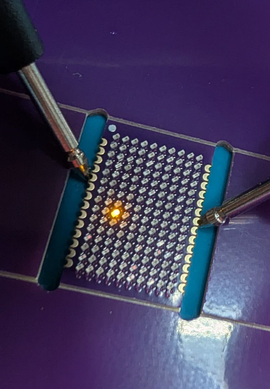
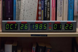
Two playable games have been implemented - variations of Pong and Snake. And also a test program - to check if the display, buttons and sound do work together. Here is a short demonstration:
Implementation details
ATTiny10 has the following specifications:
- Main clock frequency: 8MHz
- Program/data flash: 1KB
- RAM: 32 bytes
- 8-bit ADC
- 4 GPIOs
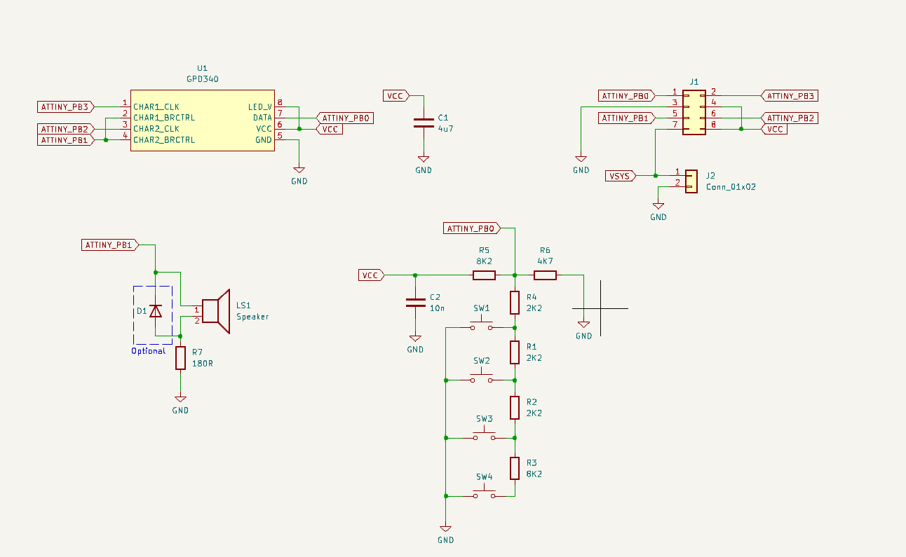
The display - GPD340 requires at least 4 output lines to control (serial data, 2 clock inputs, PWM brightness control), one output is needed to make some noise with the buzzer, and there're 4 buttons. So all these channels need to be multiplexed to just 4 GPIOs.
So I came up with the following GPIO assignment:
- PB0 - is shared between the keyboard and serial data input for the display
- PB1 - outputs the same PWM for both - brightness control and the buzzer. Most of the time it outputs high-freq (>20KHz) PWM, so the buzzer appears silent. When we need to produce a sound, we just switch to a lower frequency and adjust duty cycle so the display is not too bright/dim.
- PB2 - serial clock input for the first half of the display
- PB3 - serial clock input for the second half of the display
The buttons connected to PB0 via a resistor ladder, so each button causes different voltage levels which could be read by the ATTiny's ADC to determine which button is pressed exactly.
The game cartridge also acts as the main power switch/jumper: when inserted, pins 7 and 8 on the edge connector are shorted allowing current to flow.
The very first prototype was built on a breadboard:
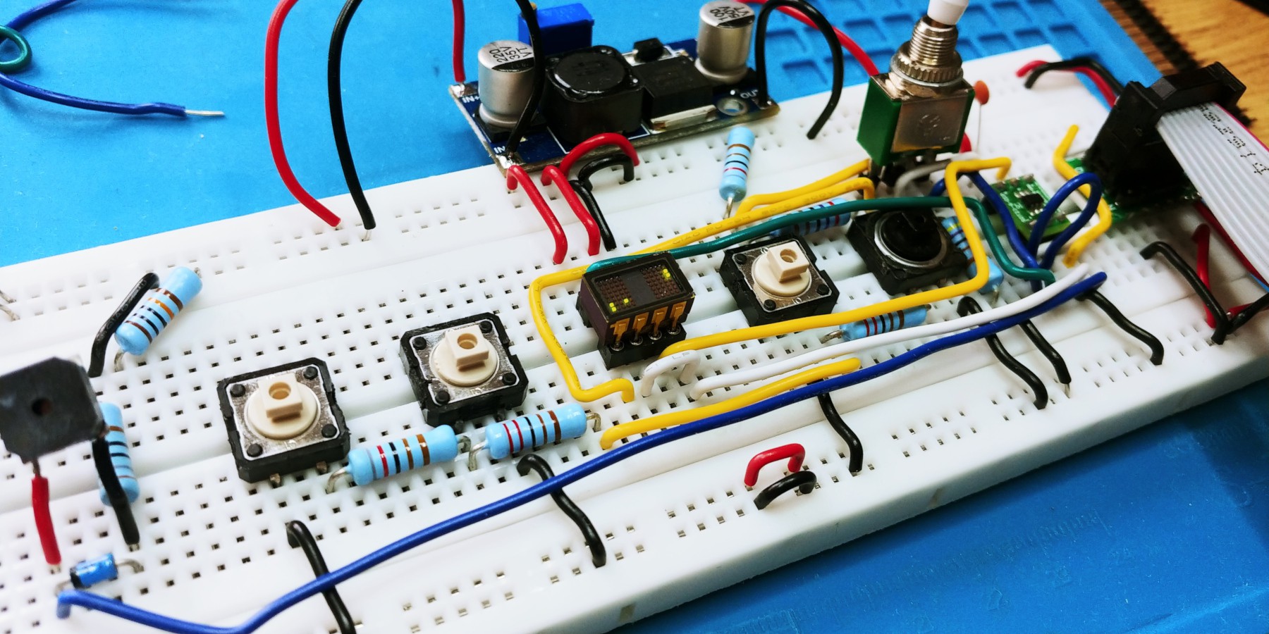
And this breadboard also doubles as a programming rig for the cartridges. There is a 12V boost converter with a switch, which is required to program an Attiny10 when the reset function on the pin PB3 is disabled.
All firmware is written in either C or assembly using avr-gcc and uploaded to the device with a cheap USBASP programmer.


 Stephen Holdaway
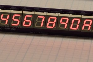
 Bharbour
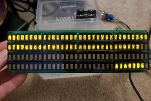
 sjm4306
 deʃhipu
Nice! I made a similar project not too long ago with the whole "cartridges as cpu + mem" thing meant to be a business card. I've been working on a new version of it, actually.