 Vladimir Todorov
-
A simple but very useful Zener diode tester
7 days ago • 0 commentsLately, I've been heavily involved in reverse engineering. Sometimes I need to check at what voltage a Zener diode breaks down. For this purpose, I built a tester. It consists of a constant current source, a general-purpose power supply, and a voltmeter. The constant current sources is simple - one Depletion MOSFET and a resistor.

Electrical Schematic of the Zener Diode Tester
The Idz current is adjusted with resistor R1. Infineon provides a very comprehensive Application Note on the operation of Depletion MOSFETs as constant current sources. Since it's an old article that is difficult to find, I will provide a download link at the end.
Application Note title: Depletion MOSFETs.
Author: Pradeep Kumar Tamma.
Document reference: AN_201410_PL11_003.
Revision 1.0, 2015-02-03.
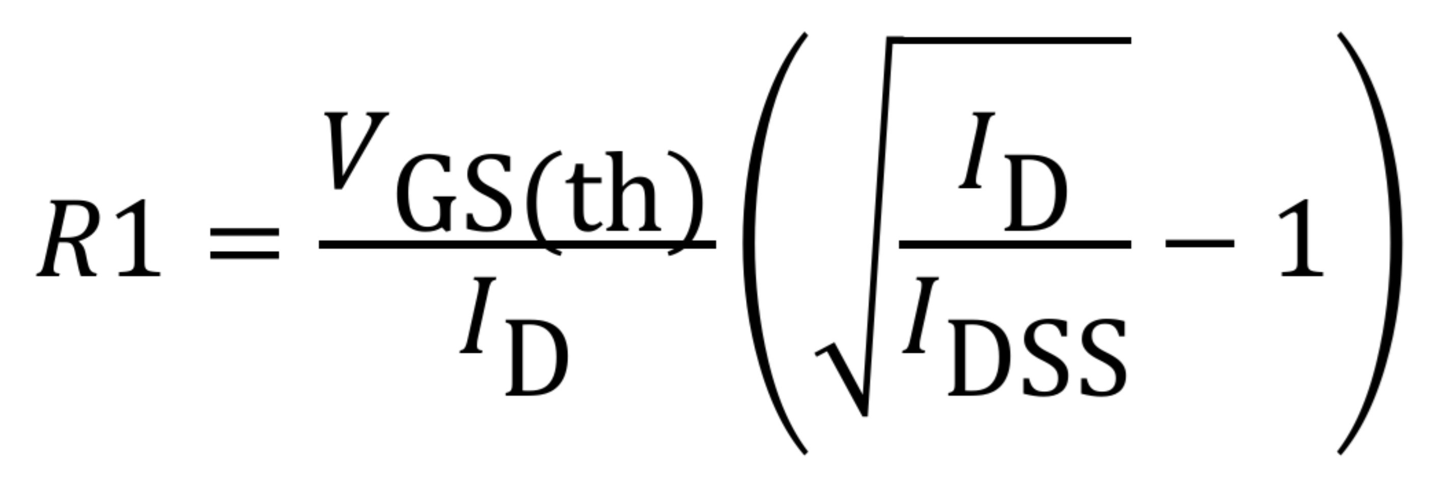
Here is the relationship between
R1 ,
Id : the desired current ,
Vgs(th) : the gate threshold voltage of the MOSFET and
Idss : the on-state current at VGS = 0 V .
![]()
According to the DN2540N5-G datasheet, VGS(th) ranges from 1.5 V to 3.5 V. Тhe minimum Idss value is 0.15 A, and the maximum value is not specified.
The table below shows the calculated values of R1 for specific values of VGS(th), with Idss and Id held constant.
VGS(th) , V Idss,A Id,A R1, Ω 1.5 0.15 0.001 1378 2.0 0.15 0.001 1837 2.5 0.15 0.001 2296 3.0 0.15 0.001 2755 3.5 0.15 0.001 3214 At the end, I have included links to ODS and XLSX files which contain the implemented formula. You can view the results and perform calculations with different values there....
Read more »
My Pages

Things I've Built
PCB reverse enginerring.
Digitally adjustable power supply.
Buck Converter with TL494 and MCP2210. The MCP2210 is used to set the reference voltage. Changing the reference voltage changes the output voltage.
FMS decoder
Monitoring FMS Vers. 01.00 ( some messagess from SAE J1939.
 Lutetium