 Marco M
Introduction
This is about making an own analog optocoupler (vactrol) and using it to make a single stage high gain amplifier.
In this circuit the vactrol is used as feedback system to stabilize the amplifier by means of negative feedback.
Schematic of vactrol single stage amplifier
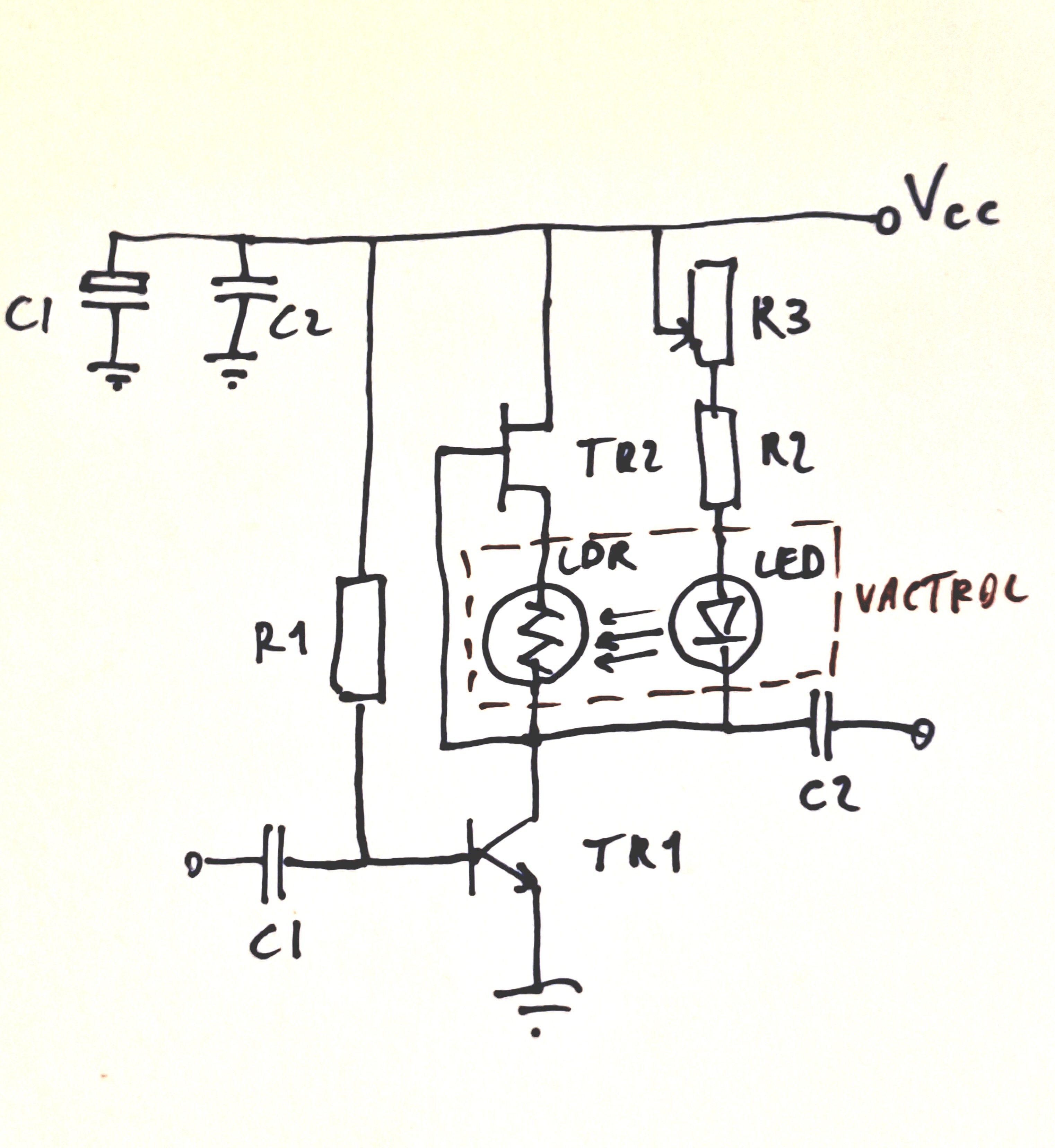
Bill of material
R1 470K
R2 2K2
R3 5K trimmer
C1 330n (see text)
C2 330n
LDR GL5516
LED see comment
TR1 2N2222 / BC549C
TR2 J113
The LED and the LRD are joined to form a vactrol (see below). You can practically use almost any typical 5 mm lamp. White LEDs of this kind are fully on at some voltage around 3 V drawing 20 mA. In my trials I reached a quarter of the maximum current - but it all depends on the efficiency of the LED. I used an Avago white LED HLMP-CW11-X1000 which delivers over 7000 mcd at just above 3 V / 20 mA, 15 deg angle meaning that most light reaches the LDR.
The thing you need to do is adjusting the value of the resistor R2 to find a good compromise between gain and thermal stability. This is further explained as follows.
Principle of operation
How does it work. The FET is used as a high impedance current source. The current depending on Vgs - the higher VGS, the lower the current. Vgs is determined by the current itself and by the resistance of the LDR. If the current tends to increase, e.g. because of the BJT thermal shift, the voltage drop across the LDR increases, reducing the voltage on the point of connection of the LED, which in turn becomes brighter. This causes the resistance of the LDR to decrease, reducing Vgs. The whole loop, if the proportion among the key electrical parameters is correct, stabilizes the collector voltage while allowing for the current to change in function of the temperature - which is not ideal, but preserves the voltage swing capability. It is a sort of servo bias circuit otherwise realized by other means - by the way, I find this article, or better said the whole site, really excellent in my view: https://sound-au.com/ism.htm.
One may wonder why the vactrol + FET circuit does not provide negative feedback on the signal. The thing is, the LDR has slow response, so, unless you are after frequencies below 100-200 Hz, you do not see noticeable effect. In any case, if you are after signals of frequency below 1000 Hz, then increase the capacitance of C1.
It is interesting to note that the voltage gain can be adjusted by changing the supply voltage. This is because the gain is proportional to the impedance of the collector network, which increases when the supply voltage is increased.
The selected FET J113 has Idss 2 mA or slightly higher.
In the trials with the 2N2222, the current through the collector was about 8 mA
This may seem a bad match for the 2N2222, which features higher current at larger collector current, and was selected to test the achievable speed of the circuit, since the initial idea was to develop an amplifier for a magnetic coil picking up signals in the range of 20-200 KHz.
But in practice,even when tested at higher collector current, the gain was about the same. The reason being that the gain depends mostly on the impedance as seen from the collector.
I did some trials with a BC549C, higher beta, and in terms of collector current vs. current gain a much better match, which confirmed the above statement.
The poor repeatability of the FET characteristics adds to other sources of variability in such a circuit - the home-made vactrol is certainly a main one. This is why some experiment with R2-R3 is required.
Trials

I used a signal generator delivering 110 mV peak at 21 KHz, passing the signal through a 1:100 resistor divider.
For the following two tests, R2 + R3 are set to provide in collector voltage 2.7 V with supply 24 V and 3.8 VDC with supply 14 VDC. This working point gives thermal stability enough for use at room temperature but far from optimal: by blowing the circuit with high temperature air from the soldering station I could produce a significant shift of the collector voltage.
With 24 VDC supply the voltage gain is about 810.
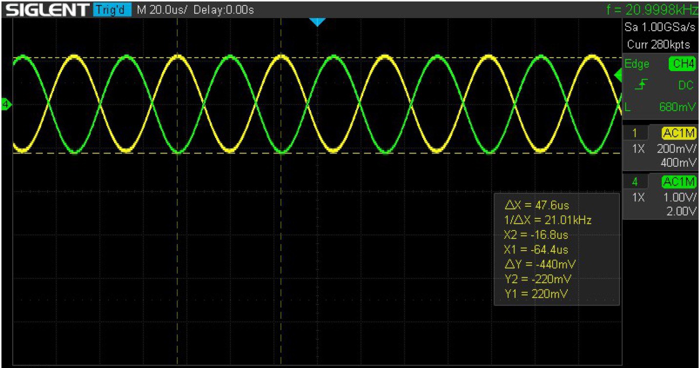
Green: output
Yellow: input x 100
At 14 VDC supply, the voltage gain is reduced to about 520.

Green: output
Yellow: input x 100
The amplifier shows a decent bandwidth as well. At 500 KHz, with 24VDC supply, the gain is about 180. The amplifier still provides decent gain at frequencies in the order of the MHz.
By setting the R2+R3 differently (about 3 K), and with 24 VDC supply, the collector voltage is raised to 7 V. That combination results in lower gain but better thermal stability, not the least much higher output dynamic range.
The collector current is near 8 mA. The voltage gain at 21 KHz is then 640 - still a pretty decent gain for a single stage amplifier. The -3dB bandwidth is about 350 KHz.
The current measured through the LED at steady-state is just below 5 mA.
Stability
When the circuit is heated up by blowing it with a heat gun, the current through the LED increases, while the collector voltage decreases, as expected. I have no equipment to control the temperature, but I could feel the devices being significantly hot, certainly more than you would ever have in a lab.
The lower stability with lower collector voltage can be explained as follows: the variation of luminosity of the LED upon variation of collector voltage is lower when the collector voltage is lower. In other words, the stabilizing feedback gain is lower when collector voltage is lower.
Input impedance
The measured input impedance is, as expected, quite low: 670 ohm. This is suitable for an amplifier to collect signals from a low impedance magnetic coil. Note that the output impedance tends to be high: such a circuit should be followed by an emitter follower or some other kind of buffer.
Test with higher beta transistor
The test with a BC549C (much higher beta than 2N2222) shows similar gain provided the same collector voltage, and similar bandwidth. The base resistor has to be increased to 1.3 M to achieve the same collector current of 8 mA.
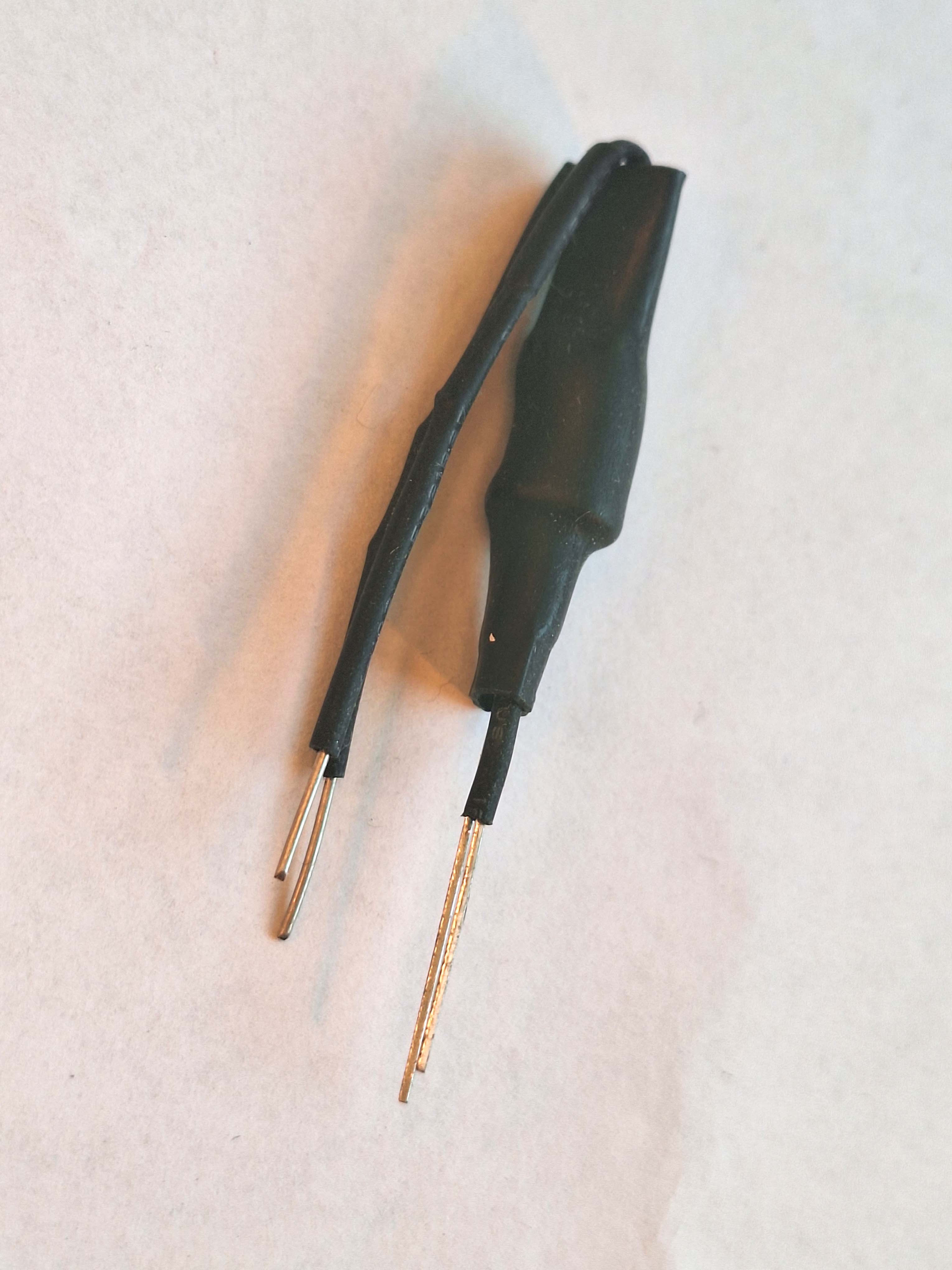
Vactrol
The vactrol is built by joining the LED with the LDR by a drop of transparent glue (I used a hot glue gun). The elements are then protected from environmental light by means of shrinking tube.


Conclusions
All in all, it is clear that the gain performance cannot be compared to that of a gain stage loaded with a current mirror.
However, I found it funny to build a vactrol and experiment with that.
I will work to improve the circuit to maximize the gain and the stability. A self-made temperature chamber will be needed to investigate the thermal stability.
Noise and distortion may be more tricky a matter but I will try to get some value.
Discussions
Become a Hackaday.io Member
Create an account to leave a comment. Already have an account? Log In.