How does it work? Consider a cable / transmission line, such as a piece of coax, with an ideal square-wave voltage source at one end (source end), and an open circuit at the other end (load end). Since the voltage source is ideal, its impedance is zero ohms – in other words, a short circuit.
The two rules to keep in mind are:
- A voltage pulse on a cable encountering an open circuit will reflect, and the reflection will have the same voltage and polarity.
- When a pulse encounters a short on a cable, it will also reflect. The reflected pulse magnitude will also be the same, but in this case it will have opposite polarity. This polarity flip is needed to satisfy the condition that a short voltage is always 0V.
Assume everything starts at 0V. The source then turns “on” to +1V. This creates a pulse on the cable that travels down the line. It eventually reaches the open circuited end, and reflects off of it, launching a +1V reflected wave back towards the source. The initial +1V pulse and its +1V reflection voltages add, boosting the load voltage to +2V.
The reflected +1V pulse travels back to the source. When the reflected pulse reaches the source, it again reflects, but at negative polarity since the voltage source impedance is zero (i.e. a short circuit). Now, if we time the source to flip polarity, to -1V, at the same instant the reflected pulse arrives, the reflected pulse and newly launched pulse from the source will have the same polarity (i.e. -1V + -1V = -2V). This causes a -2V pulse to be launched toward the open circuit (load) end of the cable. When it reaches the open circuit end, it will reflect, causing a second -2V pulse to be launched toward the source. The -2V pulse and its -2V reflection add together at the load side, now boosting the load voltage to -4V!
The -2V pulse reflected off the load then travels toward the source, where it reflects off of the source’s zero impedance, launching a new +2V pulse towards the load. Now we flip the source polarity again, to +1V. These two pulses (+1V and +2V) add, launching a +3V pulse towards to the load. When it reaches the load, it reflects, launching a +3V pulse back towards the source. The incident and reflected +3V pulse voltages add at the load, leading to a load voltage of +6V!
This process continues on and on, with the load voltage going from +2V, -4V, +6V, -8V, +10V…. and on to infinity (or until something breaks!).
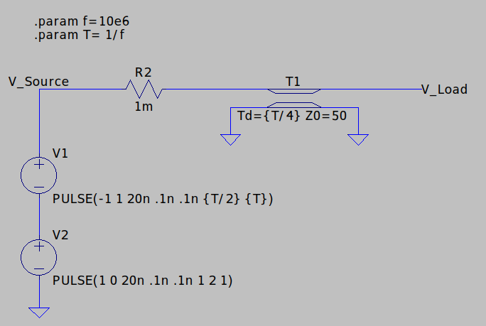
Here’s an LTspice model. The sources at left generate a 10MHz square-wave that starts at 0V, then begins oscillating between -1V and +1V. It drives an open-circuited transmission line. If you look closely at the various model parameters, you'll notice that the transmission line's time delay (Td) is set to 1/4 of the square wave's period (T). That condition generates the exact timing discussed above, where the source flips polarity right as a reflected pulse arrives back at the source.
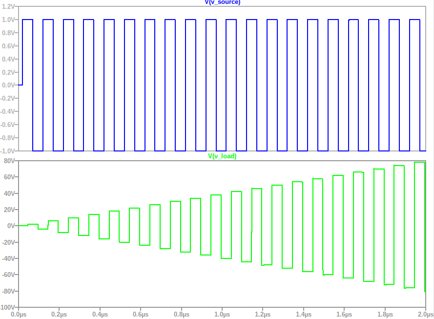
Here's the simulation output. The top trace (V_source) is the source voltage driving the transmission line. The second curve (V_load) is the voltage at the open-circuit end of the transmission line. As we predicted it grows and grows in magnitude.
This effect is used in a quarter wavelength transformer for impedance matching, but with sinusoidal signals. It also finds use in antennas, such as a 1/4 wavelength monopole or 1/2 wavelength dipole.
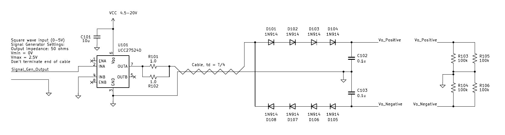
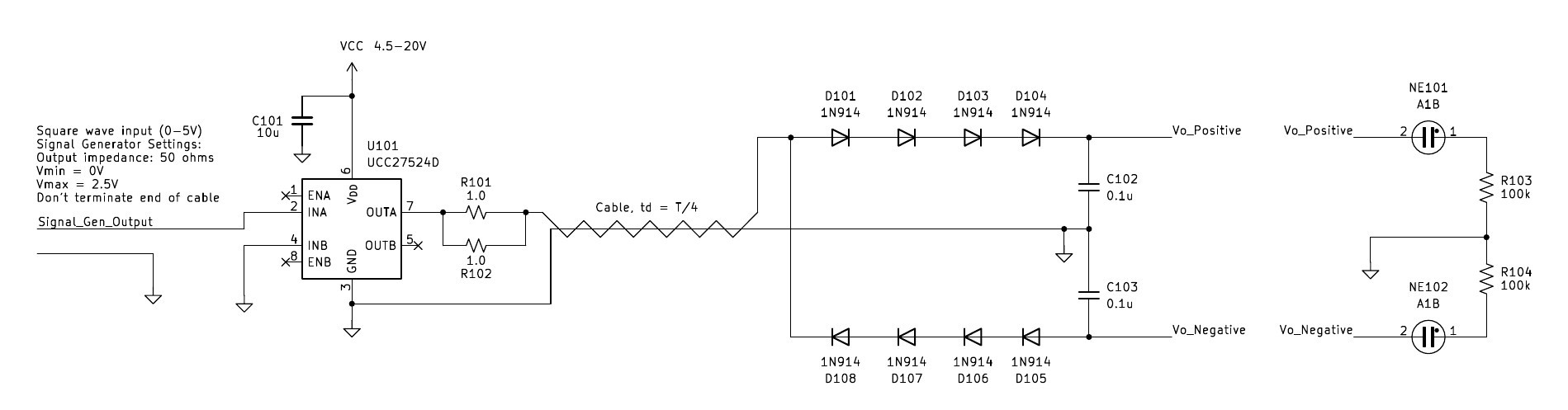
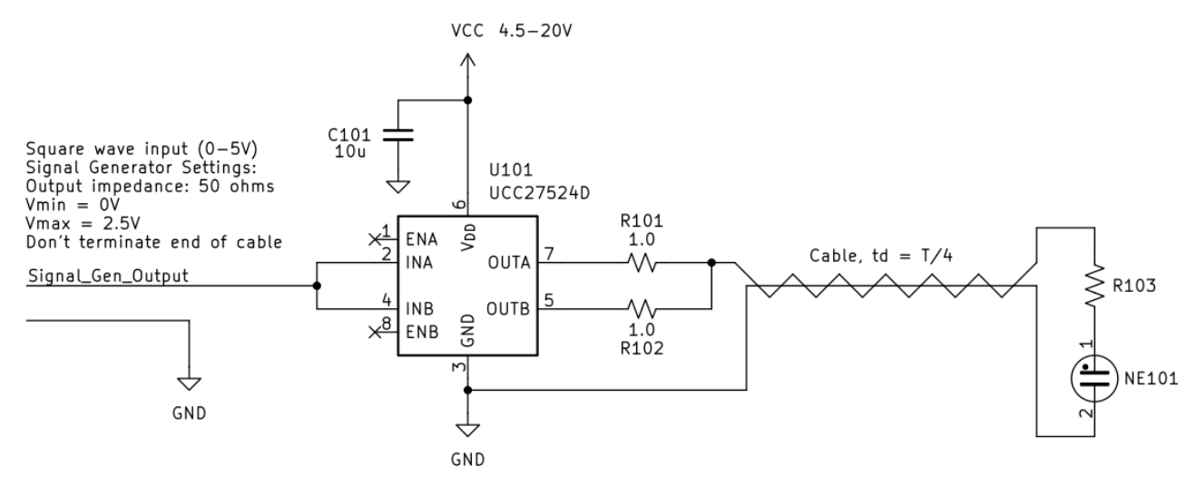
If we want to use the circuit as a power converter, to boost a voltage, we'll have some finite load resistance. We'd also have a little source impedance to account for losses in the driver (such as FET on resistance). In this case, the reflection coefficients at each end of the cable are less than one. The same voltage-boosting principle still applies. However, the output voltage will not keep...
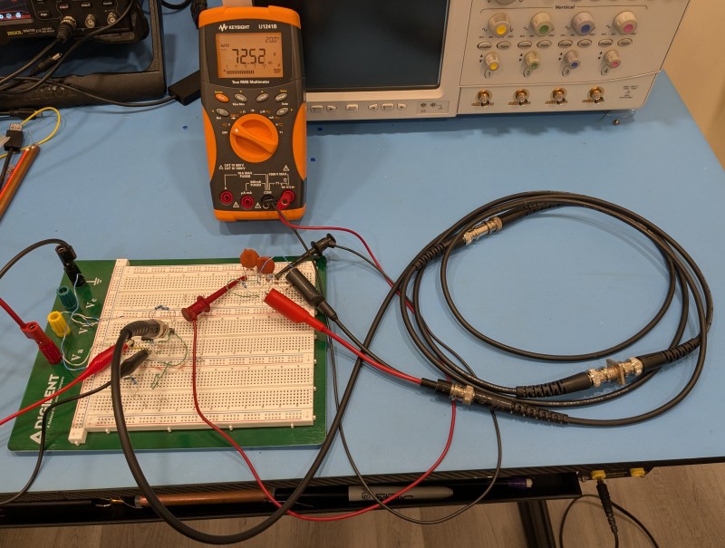


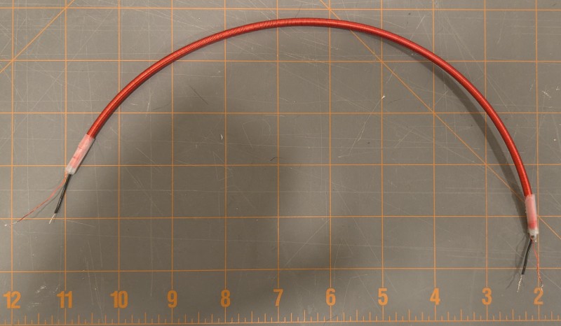 The cable's characteristic impedance worked out to about 1k ohms, which is actually a good value for generating high voltages at low power. I arrived at this value by measuring the cable's total capacitance with an LCR meter, then shorting one end and measuring the total inductance. They came out to 23pF and 23.8uH, then applied Zo= sqrt(LC).
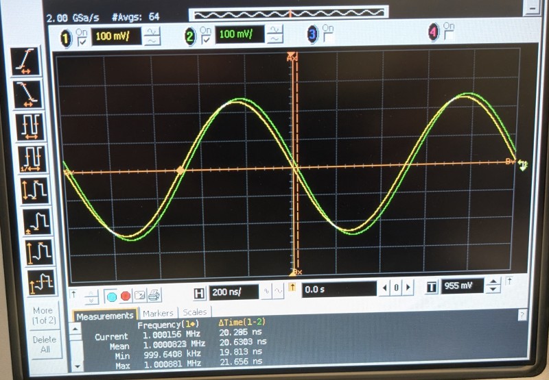 This is pretty good! A 1ft section of coax has a delay of about 1.3ns of delay, so this little section replaces 15ft of coax. The T/4 source frequency needed would be about 12.5MHz, which isn't too bad.
 w_k_fay
 Azri Jamil
 Paul Andrews