0%
0%
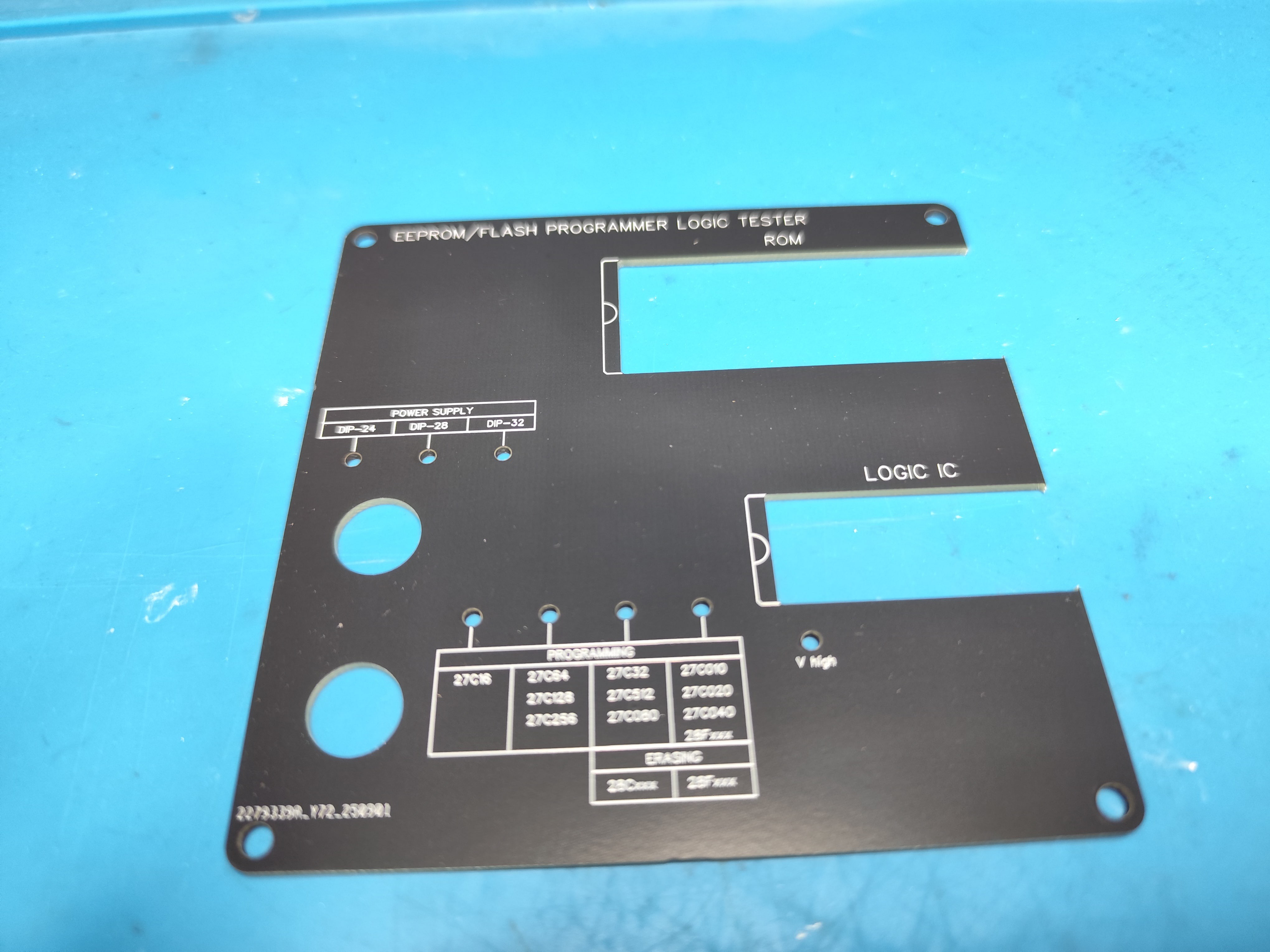
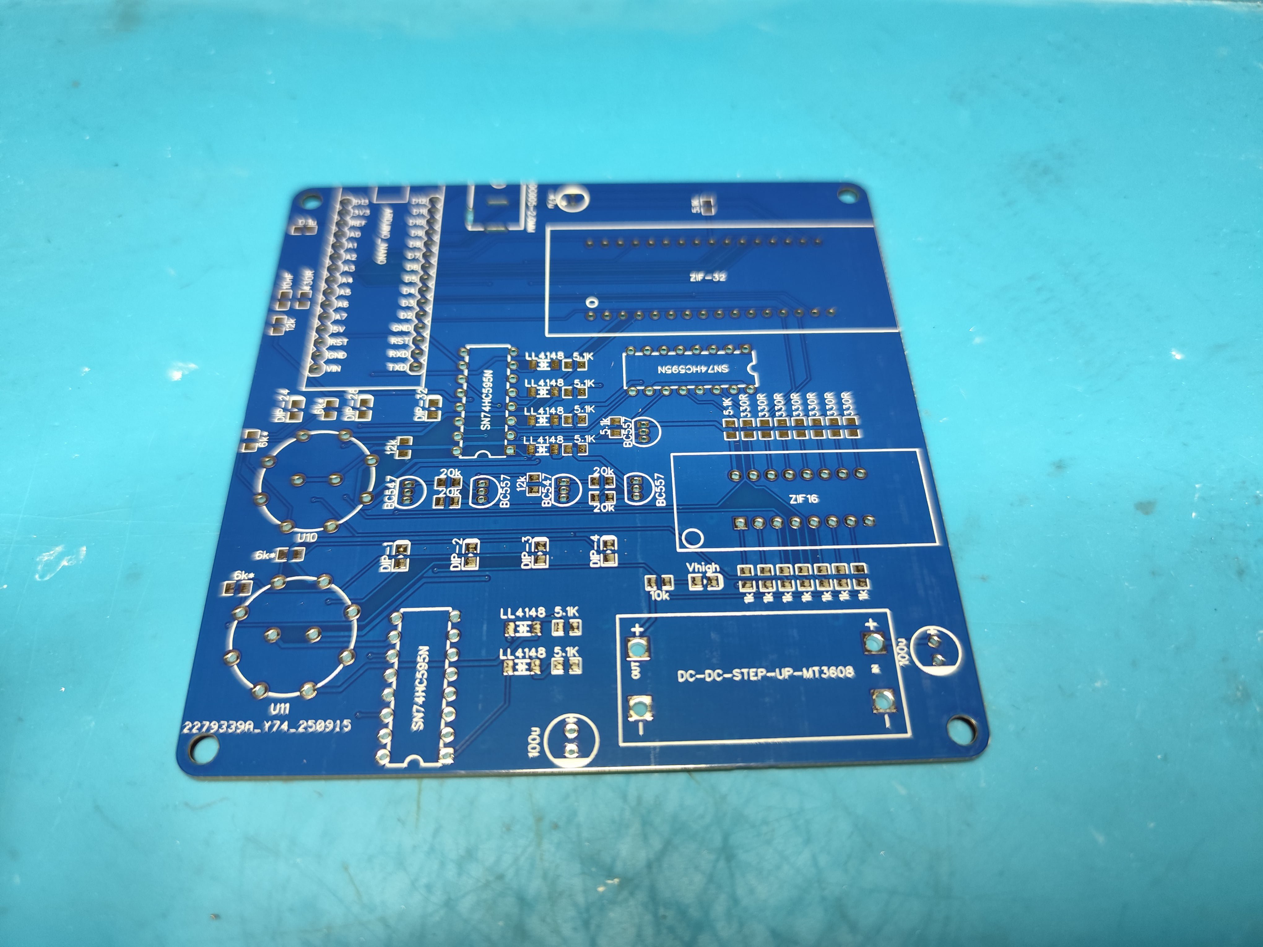
EEPROM Programmer & Logic Tester
EEPROM Programmer
 Volodymyr
Become a Hackaday.io member
Already have an account? Log in.
Just one more thing
To make the experience fit your profile, pick a username and tell us what interests you.
Pick an awesome username
hackaday.io/
Your profile's URL: hackaday.io/username. Max 25 alphanumeric characters.
Pick a few interests
Projects that share your interests
People that share your interests


 Dilshan Jayakody
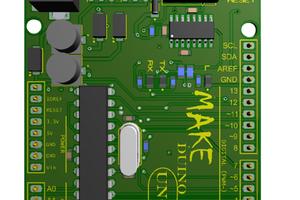
 Jefferson Bueno
 Jon Thomasson
 Augusto Baffa
Thank you so much for adding the instructions! Really appreciate it.