bornach
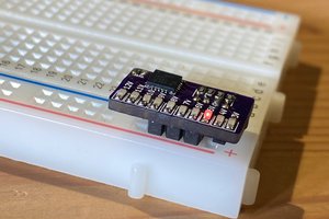
I tested a number of inductors from my junk parts bin. The one I ended up using was salvaged from an inkjet printer.
I used a standard TL431 circuit to regulate the output voltage to 5V in order to avoid damaging the microcontroller.
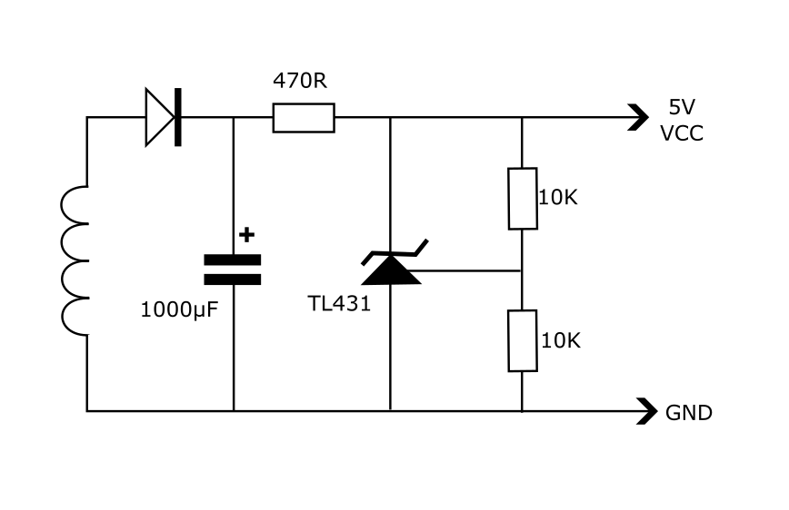
I didn't pay attention to any of the Qi standard in the design. I basically threw whatever was in the junk bin together to see what would work. So the inductor and capacitor are in no way tuned or optimised. That it works as well as shown in the video was very surprising to me because I didn't include any Qi-compliant power negotiation circuitry. I have not tried this with a different Qi charging base station--it might be that I got away with drawing the necessary power only due to this particular base station not being very strict when implementing the Qi protocol.
Reading up on the Qi charging standard, what I believe to be happening is that the base station is sensing the presence of a device that needs to be charged, by periodically sending out an analogue ping. It so happens that there is sufficient energy in this ping that, if sent frequently enough, is sufficient to power very small and less demanding circuits such as this meteor shower LED module. Of course, this board does not send the expected reply to the initial ping, so the base station never gets to negotiate the required transmission power according to the Qi communication protocol, so it just keeps pinging at a minimal power level. This receiver circuit would not be at all useful for higher current draw applications such as charging a battery.
But this does demonstrate that some Qi charger transmitters can tolerate a certain amount of abuse when using the most rudimentary of receiver circuits.

 SimpleTronic
 Silícios Lab
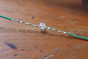
 Martin