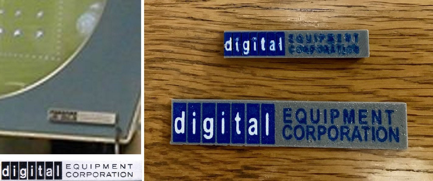
Close
0%
0%

DEC Precision CRT Display Type 30 Reproduction

Obsolescence Guaranteed just released their new PiDP-1 Replica. While I wait for mine I thought I would make a 2:3 scale Type 30 Display.

Similar projects worth following
When Oscar Vermeulen released his PiDP-8/I reproduction I knew that I had to have one. When I got mine assembled I thought it would be cool to connect to it through a period-ish terminal so I created a 2:3 Scale VT100 Reproduction. Now Obsolescence Guaranteed has released their new PiDP-1 Replica. While I wait for mine I thought I would make a 2:3 scale DEC Precision CRT Display Type 30 Reproduction to go with it.

Screen Design

The 19 inch CRT inside the Type 30 was used primarily for radar screens. Not many of those kicking around any more or for that matter CRTs of any size.  While there are a number of round LCD screens available today they come in two flavors, small and relatively cheap, or large and prohibitively expensive.  So finding a round screen for this project is probably not an option. That leaves trying to fit a square screen into a round opening. Since I knew that this would be the key to making a good reproduction I put some work into the design.

From the Precision CRT Display / Type 30 Manual the following page provides some key information towards a design.

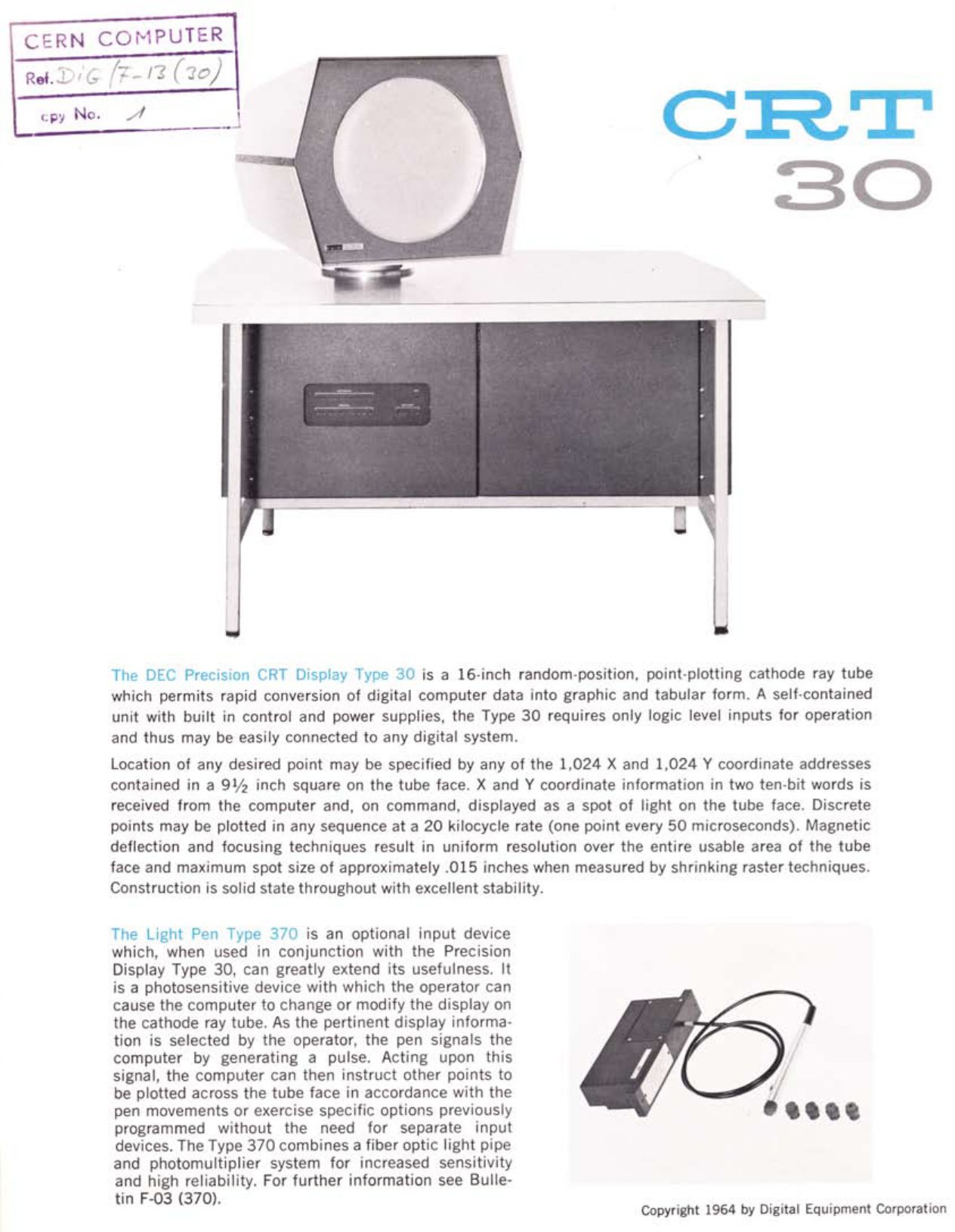
From the first paragraph we learn that:

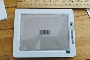
  • the screen opening is 16" in diameter,
  • that the screen resolution is 1024 x 1024 pixels, 
  • and that the active area of the screen is 9.5 inches square.

Knowing that the circular opening is 16" helped me to scale my model properly. By bringing in a photo of the Type 30 as a "background" Canvas to Fusion I was able to calibrate the image to proper mm coordinates (sorry I'm Canadian). Since I am doing a 2:3 scale model the screen opening becomes 270 mm in diameter. With that as a starting point I roughed out the front face of the Type 30 in Fusion.

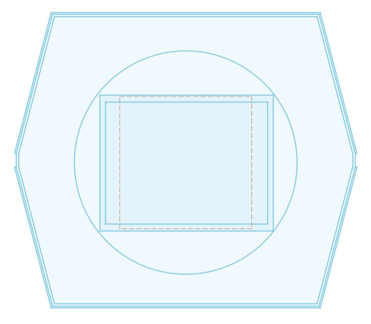
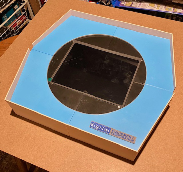
Outside hexagonal lines define the walls of the monitor. The inside most hexagon and the imbedded circle make up the mask that sits in front of the "CRT tube". Nested in the circle the dotted square marks the active 9.5 x 9.5 inch area of the screen in the original (or in my case 160 x 160 mm at 2:3 scale). The other two solid rectangles represent the outside and screen dimensions of a 10-inch LCD Screen Kit (1024x768) that I found. Since it's a 4:3 screen the fit is almost perfect for this project. 

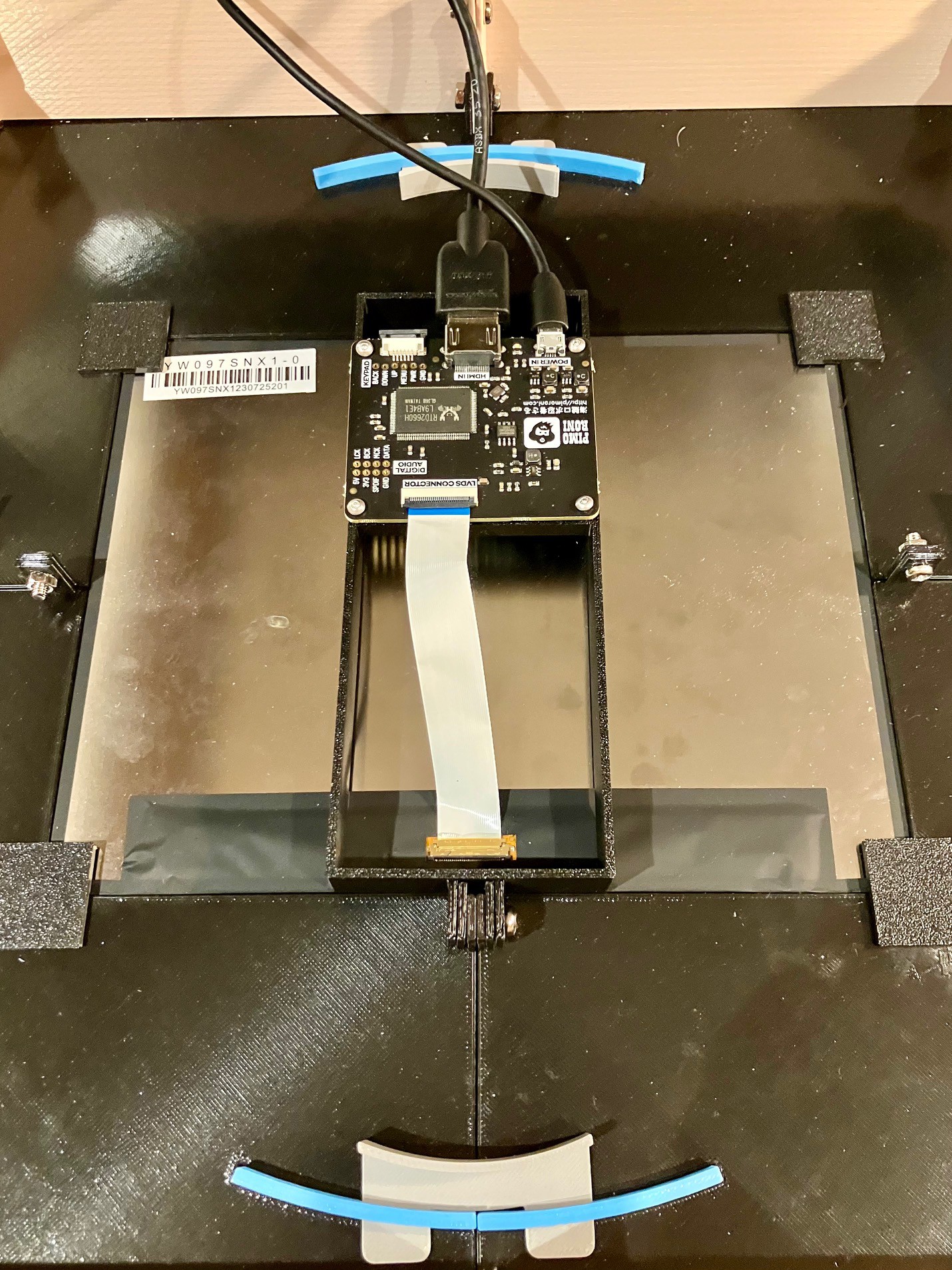
So here is the plan.

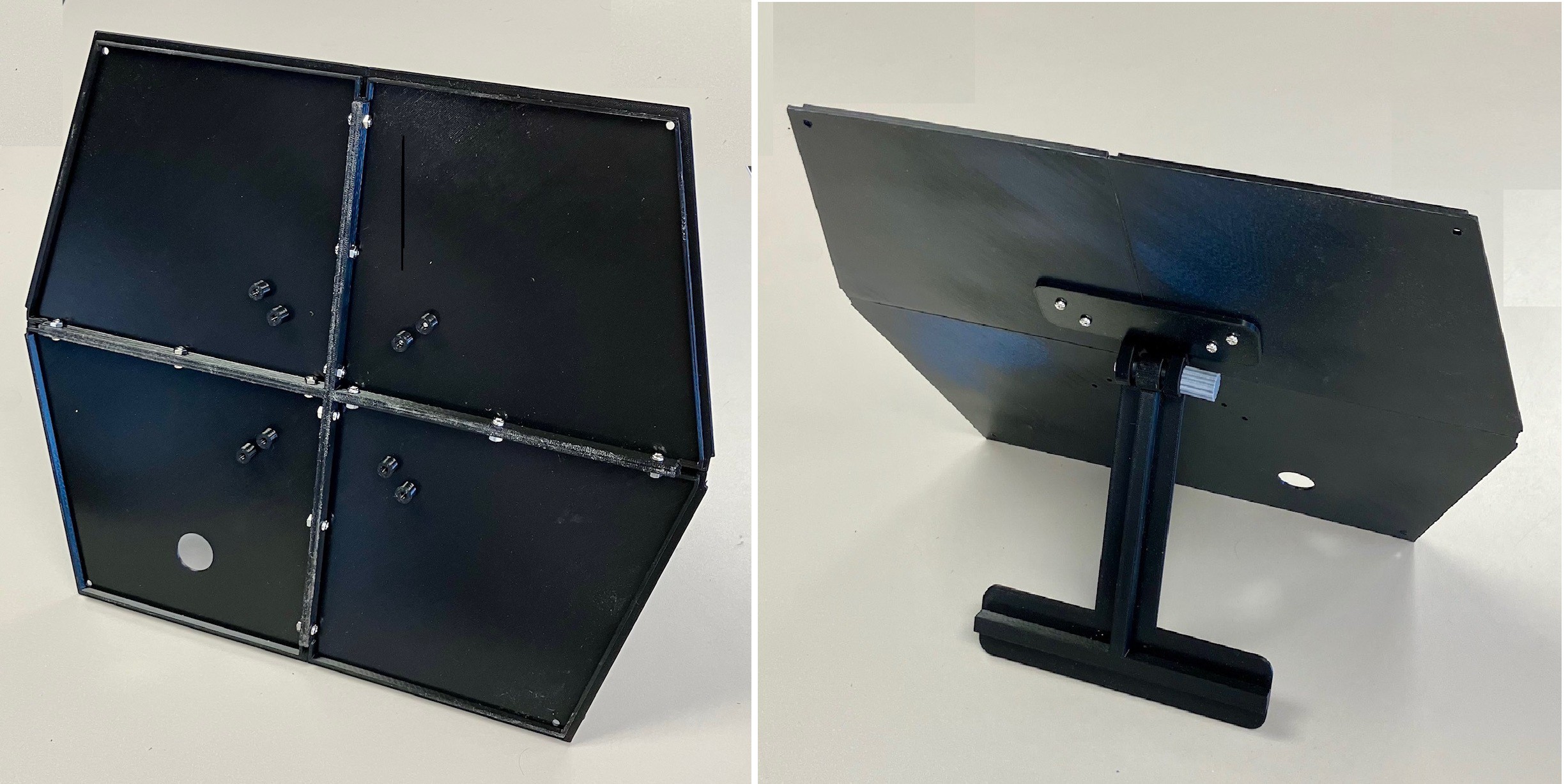
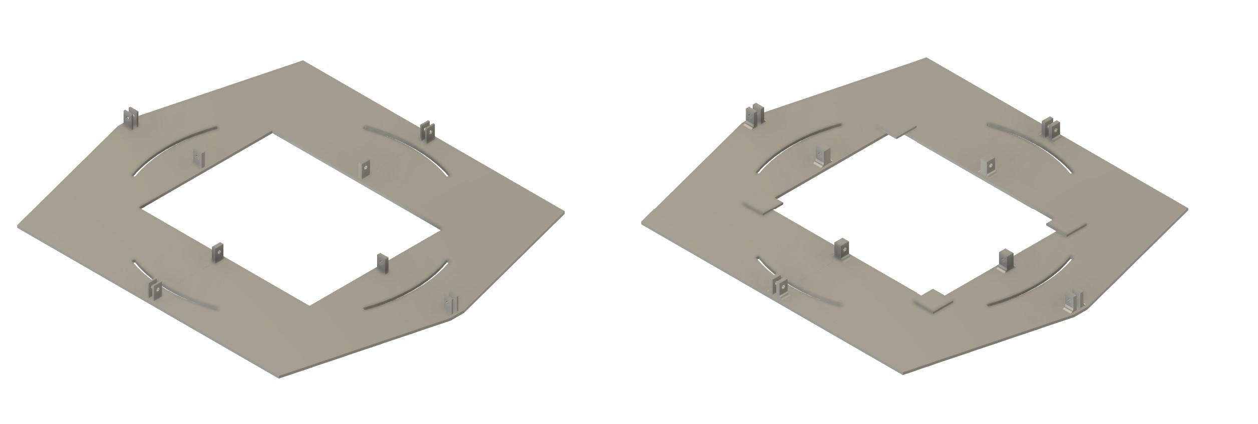
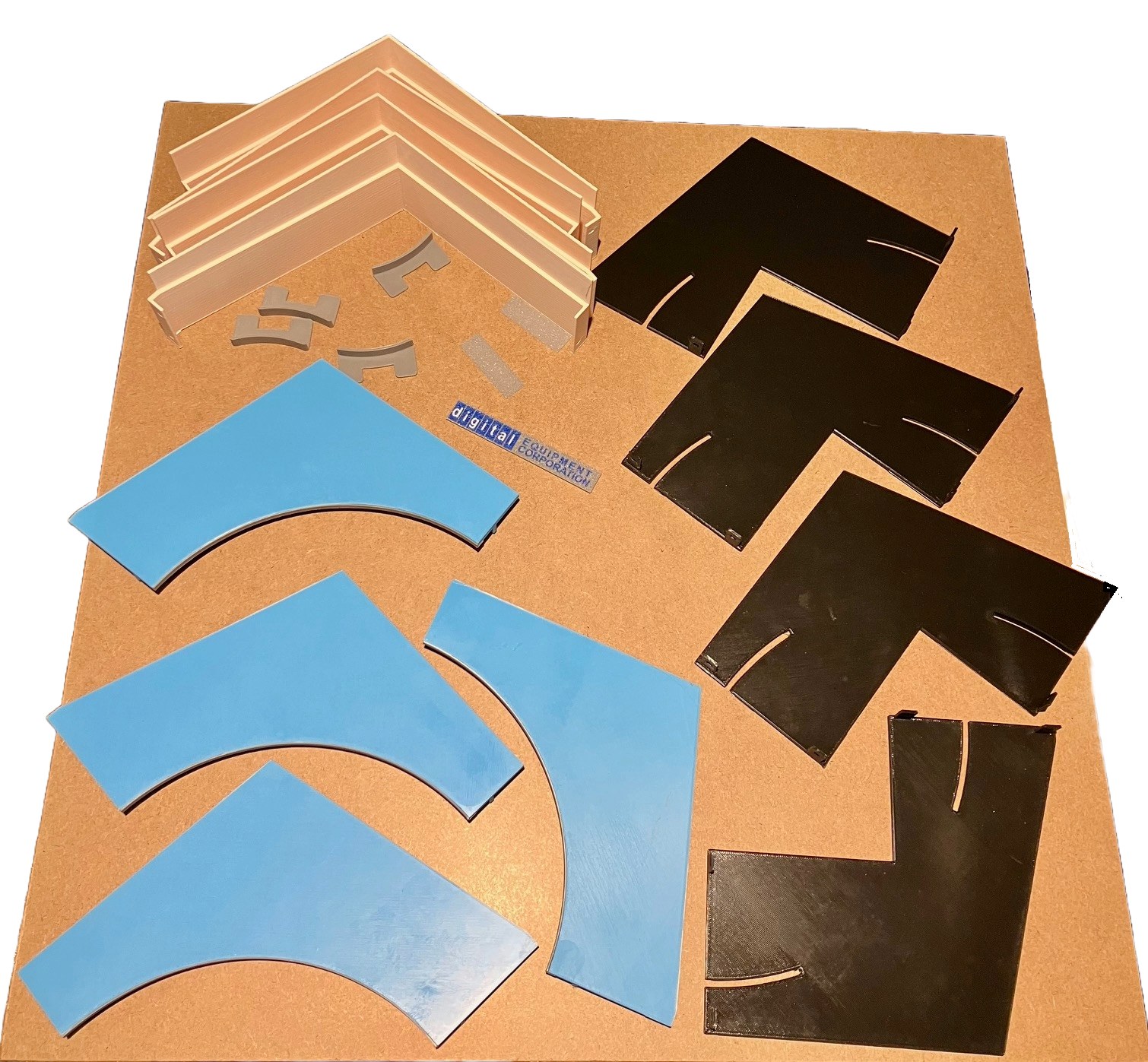
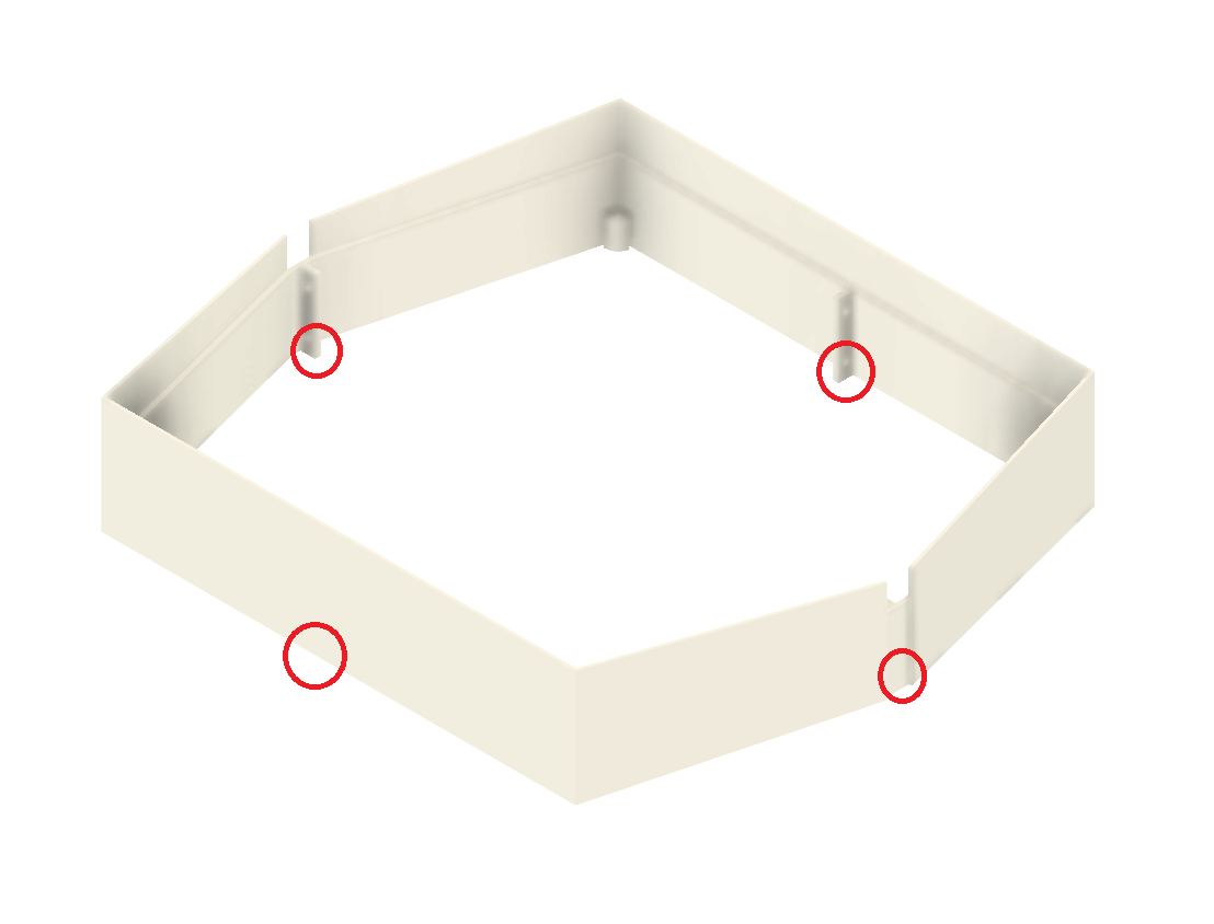
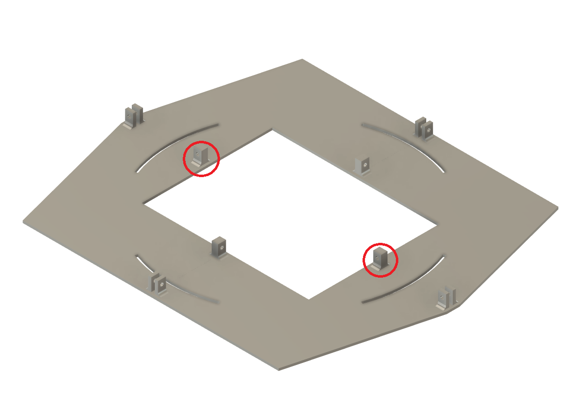
The Front Face is a stack (left above) made up of the following layers numbered from top to bottom.

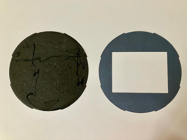
  1. Screen mask that frames the "CRT display". 
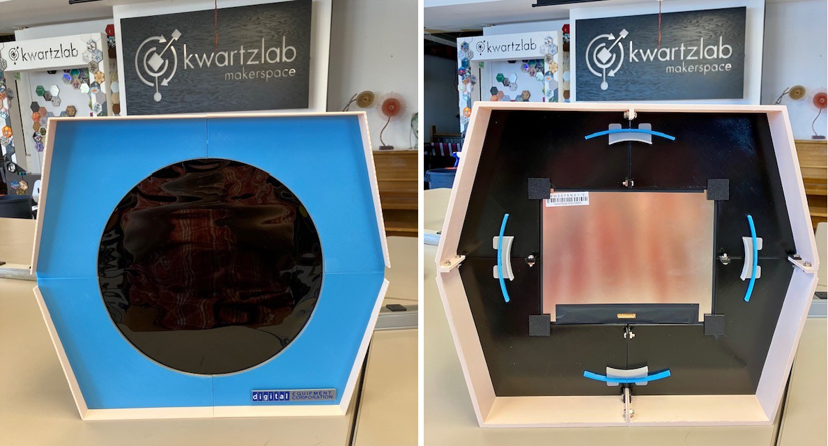
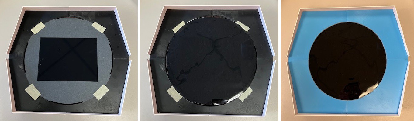
  2. A "filter" that is opaque enough to hide the fact that there is a rectangular screen imbedded in the next layer but translucent enough so that the screen below can be seen through when active.
  3. Frame to secure the LCD panel. The panel surface will be flush with the top of the frame so that it comes in contact with the filter layer above it.
  4. An LCD screen.
  5. The Type 30 case (shown in part here).

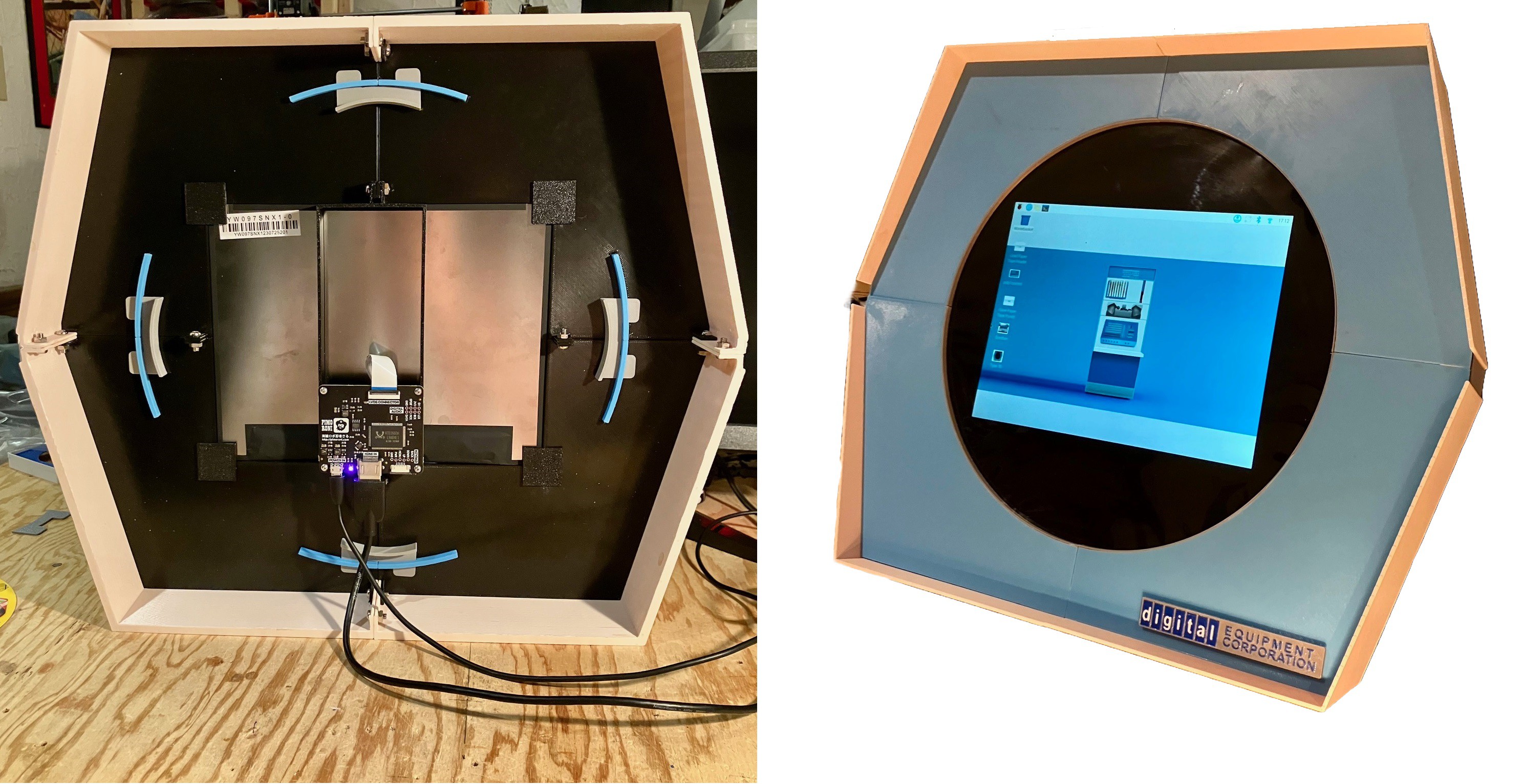
On the right above an "assembled" screen.

With this in hand I'm comfortable enough to order the LCD panel. While I wait for that I'll get the PiPD-1 software going.

This is going to be fun. 

Screen Mask Rim.3mf

3D Model for the silver rim the goes inside the Screen Mask circular cutout.

3mf - 7.24 kB - 09/30/2025 at 14:20

Download

Logo.step

Generic 3D modelling file for the Logo badge.

step - 1.70 MB - 09/29/2025 at 18:49

Download

Logo.f3d

Autodesk Fusion 3D modelling file for the Logo badge.

fusion - 1.82 MB - 09/29/2025 at 18:49

Download

Front Face.f3d

Autodesk Fusion file for the front part of the display. Includes the Case Sides, Display Holder, Screen Mask, Screen Mask Locking Wedge, and Side Groove Cover, Screen Mask Rim.

fusion - 926.55 kB - 09/29/2025 at 18:49

Download

Front Face.step

Generic 3D modelling file for the front part of the display. Includes the Case Sides, Display Holder, Screen Mask, Screen Mask Locking Wedge, and Side Groove Cover.

step - 596.49 kB - 09/29/2025 at 18:49

Download

View all 24 files

  • 1 × PIMORONI HDMI 10" LCD Screen Kit (1024x768) This is a 4:3 aspect ratio panel that works better as a backing for the Type 30's round screen. Available at PIMORONI: https://shop.pimoroni.com/products/hdmi-10-lcd-screen-kit-1024x768?variant=21253917704275
  • 2 × MOEN 1/2" Flat Washers M3861 OPTIONAL: Only required if to print the hinged "stand" for the back of the reproduction.
  • 1 × Colored Gel Sheet To go between display and round mask. Amazon: https://a.co/d/1J04b3m
  • 4 × M4 x 16 mm Bolts and Nuts Join the case walls and screen holder frame together.
  • 4 × M4 x 10 mm Bolts and Nuts Join the screen holder frame pieces.

View all 9 components

  • Adjusted The Display Card Holder

    Michael Gardi10/05/2025 at 00:41 0 comments

    When I designed the Display Card Holder as a way to mount the Display PCB and installed it, there were a couple of things that I was not completely happy with.  First of all I had the ribbon cable between the PCB and Display installed wrong so when I corrected it there was a twist in the cable. It still worked but it put unnecessary strain of the connections. The other thing was that the display as it was installed was upside down. Again not a big deal but it meant that I had to go into the Raspberry Pi settings every time I made a change and configure the screen to be inverted. So I redid the Display Card Holder to correct these issues.

    I have updated the build files with these changes.

  • Cable Management

    Michael Gardi09/25/2025 at 20:07 0 comments

    My Back Panel just has a 25 mm hole through which to pass an HDMI and a USB power cable to the display.  Gets the job done but looks a little messy.  So to clean that up a bit I modeled a plug with some cable channels. This will also help to mitigate any damage to the display electronics should the cables get inadvertently yanked.

    An even cooler way to go would be to add panel mounted HDMI and USB connectors and wire them to the panel electronics. I'm OK with this way foregoing the expense of that additional hardware.

    When I get to the point of adding embellishments like this to a project it's time for me to wrap things up. So onward to posting build files and polishing up the documentation.

  • I'm Baaaack

    Michael Gardi09/24/2025 at 20:05 0 comments

    With the display part of the project well in hand I had to decide how far I was going to go with the reproduction. I have been leaning towards not building out the rest of the case, mainly because of the size of the Type 30 even at 2:3 scale.  Here is a side view that I found.

    I estimate that at 2:3 scale the sides would be about 20 inches deep. The original was probably closer to 26 inches (and I don't even want to think about how much it must have weighed). For my reproduction this would be wasted space since there is no CRT required. I can't think of where I would be able to actually use it in my cluttered workspace. So I have decided to "chop off" the back part and make my Type 30 reproduction more like a monitor.

    To that end I modelled a back plate to finish it off. 

    Again wishing for a printer with a bigger build plate, the back was printed in four parts and bolted together. Thanks to a great suggestion from Glenn Babecki over on the PiDP-1 Google Group I have added reinforced holes so that a 75/100 VESA monitor stand or a wall mount could be used to support it.  I also printed a locking hinged arm (based on this design) much like a desktop photo frame that bolts onto the VESA holes.

    So with the back on here is what it looks like.

    I think that just reproducing the front 10% of the display provides 90+ % of the user experience. 

  • Snowflake Demo

    Michael Gardi09/22/2025 at 03:14 0 comments

    I had a chance to get into the PiDP-1 software today. It's pretty cool. There's a lot there to get your head around because Obsolescence Guaranteed is basically recreating the whole PDP-1 ecosystem from the early sixties running on a Raspberry Pi 5. As part of that effort they are recovering the "paper tape" images for numerous demos created for the PDP-1 at the dawn if the computer era.

    So I fired up a virtual PDP-1 Console (which will be replaced with the physical PiDP-1 down the road), loaded up a virtual tape drive with a recovered "snowflake" demo tape image, and "hit" the virtual READ IN switch on the console. After a little virtual  "blinken light" action the output appeared "full screen" on my Type 30 reproduction.  Here is what it looks like.


    If you look closely you can see the faint outline of the 4:3 LCD screen. I think if I use a darker gel filter I can eliminate that or at least mitigate it further.

  • Let There Be Pixels

    Michael Gardi09/20/2025 at 23:04 2 comments

    I modelled a "bridge" with a platform to mount the display electronics.

    It bolts to existing tabs on the display frame. I attached an HDMI cable from the Pi 5 that I have with a fresh PiDP-1 image. I'm powering the display from one of the PI's USB ports. So far so good. Flicked the power switch and nothing happened. Figured out that the ribbon cable between the display and the electronics was reversed so I fixed that and voila. Well actually the screen was upside-down so I had to update the Pi's Windows Config, but then I saw the image shown below.

    So far I'm happy with the way the screen looks. Since I just installed the PiDP-1 image I have not yet had time to figure out how to run a "full screen" demo. Stay tuned.

  • More Assembly Details

    Michael Gardi09/19/2025 at 21:24 0 comments

    So here is what I have so far now (with a little call-out to my wonderful local makerspace Kwartzlab).

    Pretty happy with the overall look. I like the colors. I think it's a pretty close approximation to  the front three inches of a real Type 30 (at 2:3 scale). Not sure if I want to model the rest at this point. We'll see. I won't be able to improve on the fidelity without getting hands on measurements. If I do get some better measurements the model should be pretty easy to update with any refinements. 

    I'm noticing that the black ND gel is pretty flimsy. As a result you can see some wrinkles forming. I'll have to do something about that as it destroys the illusion of a glass surface. We have a bunch of 1 mm clear acrylic at the lab that was left over from the Covid days when we were making face shields. Perhaps a layer of that will do the trick, or finding thicker gel filters.

    In the back image you can see a few more construction details. For instance the blue front panel is attached via curved tabs pushed through the display holder frame, which are in turn locked in place by more tabs through slots (four grey bench shapes above). Everything else is bolted together with M4 bolts and nuts. When I was putting everything together I had a hard time because the bolt holes were a little tight, setup more for self threading than straight bolting. This was a problem because all the bolts had to be laboriously screwed in (all 12 of them, my wrist still hurts ;-). They were too close to the walls of the case and for the side parts at an angle.  Sooo I update the model with bigger holes. Should anyone want make one of these "you're welcome".

    There is only one little place where I used a bit of glue. It's hard to see in the picture above but the inside rim of the circular screen opening has a metal highlight (Silver PLA filament). This was glued in place. Even the Logo above is held in place with two sided tape (but I'm thinking about adding some joiners).

    That's about it. Time to fire up the display.

  • Sight Of Hand

    Michael Gardi09/19/2025 at 20:44 0 comments

    With the Type 30 mostly together the thing that jumps out at me is that I have obviously installed a square screen into a round opening.

    The question is how do we fool the eye into thinking it is looking at a simple round screen? I don't know the answer for sure but I have some ideas. Today I tried this. I created a couple of filters.

    On the right above is a matte black piece of heavy construction paper with a cutout for the display that exposes just the active area of the screen.  This has the effect of hiding all the seams and the non-active edges of the display. The edge of the cutout is "keyed" to the slots used to attach the blue front panel. I used a bit of tape to hold the cutout in place until the blue panel pieces are attached (left below).

    On top of that goes a Lighting Neutral Density Gels Filter (left above), which is supposed to reduce the amount of light getting through without affecting the color (middle below). It looks a little weird in the photo above but in person looks just flat glossy black.  I'm flying blind here.  I don't know how well this will work, but so far it seems to do a good job of hiding the rectangular display frame. I expect this process to be iterative until I get the effect that I want. I am looking for a similar filter in green to better represent the Type 30. 's heritage.

    Finally the blue face plates are installed holding everything in place (left below).

    Next step is to fire up the display an see if this idea maintains the illusion of just a round screen. 

  • Initial Assembly

    Michael Gardi09/17/2025 at 18:34 0 comments

    The printed pieces went together pretty well. The bolts are still a little loose so I'm hoping the seam lines are a little less noticeable when everything is tightened up. (I think I'm getting a little carried away with the Adobe "remove background feature",  or maybe I just don't want anyone to see my messy work area. ;-)

    I'm happy with everything except maybe for the black frame that holds the display in place. For sure the tabs used to bolt the pieces together are too flimsy. I managed to break one doing the assembly. As you can see the display fits in quite snugly. I am still waiting for the gel filters that will sit between the display and the blue screen mask to hide the display outline. Right now the four metal tabs with screw holes (on the display) are the only thing keeping the display from falling through to the back. The screw holes are pretty small plus I don't want screw heads sticking up as ideally the display should be pressed directly against the filter to prevent the image from being distorted.  So for my own piece of mind I will be adding some supports on the back of the frame to hold the display in more securely. I will also probably use some black electrical tape to the front edges of the display to keep it in place and to help blend the frame in with the background better. Here is the updated frame model.

    Original on the left, and on the right a model with stronger tabs and some platforms at the corners of the opening for the display panel to rest on. Rather than reprinting mine I will live with the tabs as they are and glue on some corner supports that I will print separately.

  • Printing Done

    Michael Gardi09/17/2025 at 16:30 2 comments

    In total all the parts took 60 hours to print. For now I'm done setting my alarm for 3:00 AM in order to kick off the next print.

    When I do a large sized project like this I keep wishing I had one of Ivan Miranda's large format printers. In making due with what I have though I have gotten better over the years at creating pieces that can be easily bolted together (my early projects often involved a lot of gluing). 

  • Logo Stuff

    Michael Gardi09/16/2025 at 15:08 0 comments

    The modeling went well. While I was waiting many many hours for the printing to finish (even a 2:3 scale the front of this monster monitor is about 16" x 14") I decided to make the logo that appears in the lower left corner of the display. 

    I took two cracks at making the logos by modeling then 3D printing them. On my first try I created the logo at 2:3 scale. As you can see from the smaller version above the fidelity is not great. Creating text using a .4 mm nozzle is not the easiest. So I upped the size to 1:1 scale. Much better but even at this size I had to make the "EQUIPMENT CORPORATION" text a little larger than the original. Still I'm pretty happy with it. I might try again at some point by laying out the logo in Inkscape, printing it on a matte transparency, then using clear two sided tape to mount it (a technique I have used successfully in the past).

    So here is a little tease of what's to come. 

View all 10 project logs

  • 1
    Print The Parts

    Print the parts with no supports and the following settings unless otherwise instructed. 


    Print Resolution: .2 mm 

    Infill: 20% 

    Perimeters: 3 

    Filament: I used PLA 

    Colors: Light Blue, Black, Beige, Grey

    Notes: Print the parts in their default orientation. 


    To make a Type 30 Reproduction you will need to print the following parts: 


    - Case Sides (printed as four pieces)

    1 - Screen Mask (printed in four pieces)

    4 - Screen Mask Rim

    4 - Screen Mask Locking Wedge

    1 - Display Holder (printed in four pieces)

    1 - Display Card Holder

    1 - Back Panel (printed if four pieces)

    1 - Back Stand (optional)

    1 - Logo (designed to be printed in three colors)

    2 - Side Groove Cover

    1 - Wire Holder Plug

  • 2
    Assemble The Sides

    Connect the fours Side pieces together with M4 x 8 mm bolts and nuts. For now just use the bottom four holes as shown above.

  • 3
    Assemble The Display Holder

    Start Connecting the four Display Holder pieces together with M4 x 10 mm bolts.  For now just use the two holes as shown above.

View all 12 instructions

Enjoy this project?

Share

Discussions

Andy Geppert wrote 09/22/2025 at 03:00 point

Very inspiring. Looks awesome!

  Are you sure? yes | no

Michael Gardi wrote 09/22/2025 at 04:50 point

Thanks Andy.

  Are you sure? yes | no

jeremy.geppert wrote 09/17/2025 at 02:23 point

SO MUCH YES!!!!  I'll be anxiously following your progress. I have a PiDP/8 that needs a proper display and even went as far as jotting the idea of making a replica type 30 display down in my project ideas book. Best wishes on the progress. It's looking REALLY good.

  Are you sure? yes | no

Michael Gardi wrote 09/17/2025 at 02:39 point

Thank you so much Jeremy. I too have a PiDP/8 and am looking forward to the PiDP-1. 

  Are you sure? yes | no

Similar Projects

Does this project spark your interest?

Become a member to follow this project and never miss any updates