 Arnov Sharma
Powered by the Raspberry Pi Pico W and the SGP40 gas sensor, this device goes beyond traditional air monitoring.
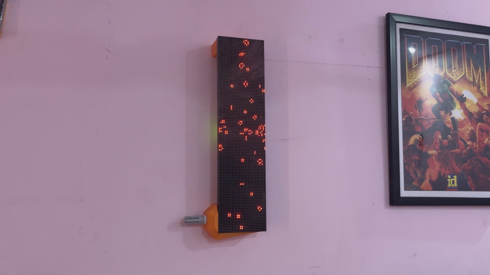
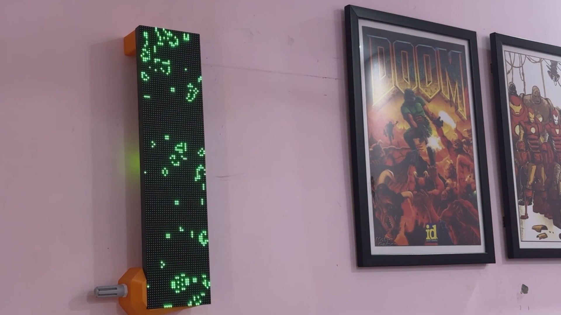
The display provides immediate, clear feedback as the air quality varies by changing its color from a soothing green to a warning yellow to a bright red. The experience is made more interesting and informative by the availability of live TVOC data via a simple web app, which is made possible by the Pico W's onboard Wi-Fi.
It combines interactive design with environmental awareness in a small, wireless package! and this article presents the simple steps you can take to develop this project. And now let's begin the build process.
MATERIALS REQUIRED
These are the materials used in this project:
- Custom PCBs (provided by PCBWAY)
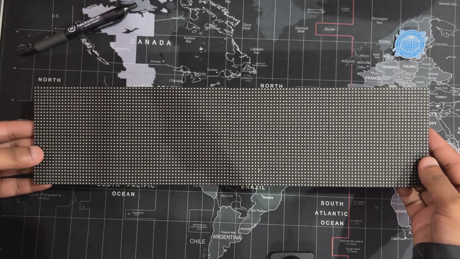
- RGB P3 64x32 Matrix Board
- Raspberry Pi PICO W
- IP5306 IC
- 10 uF SMD Capacitors 1206 Package
- USB Type-C Port
- 3D-Printed Parts
- Li-ion Cell 3.7V 2200mAh 18650
- 18650 Cell holder SMD version
- Connecting Wires
- SGP40 Gas Sensor PG7 Probe
PREVIOUS PROJECT—PORTABLE AIR QUALITY METER
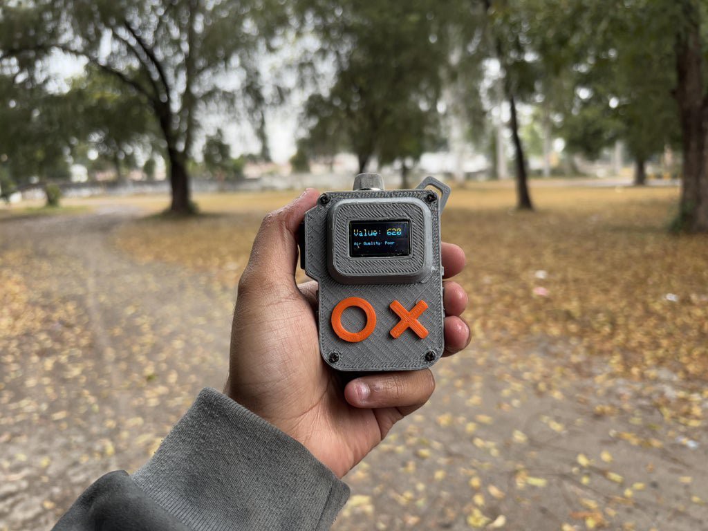
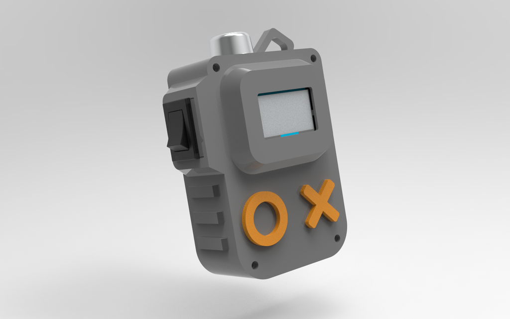
Here's a quick recap of how this project got started:In order to monitor the AQI levels in my locale, I made a very basic version of an air quality meter that uses an MQ135 gas sensor to monitor air data such as the detection of smoke, CO₂, nitrogen oxide, ammonia, etc. in the atmosphere. The data is then displayed on an SSD1306 OLED display. This setup worked, but it only showed the amount of harmful gases suspended in our environment, not the actual AQI readings.
https://www.hackster.io/Arnov_Sharma_makes/portable-air-quality-meter-64d7c6
After revisiting our approach, we found the SGP40, a top-notch AQI sensor that provides real-time air quality readings and excels at detecting Total Volatile Organic Compounds (TVOC).
DESIGN
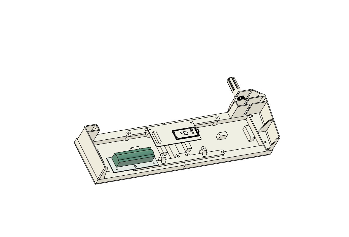


To begin the project, we created a 3D model utilizing the same two Matrix panel arrangement used in our previous Snake game max project.
In that project, we created two frame-like parts that connect two matrix panels to form a single, very long panel by attaching the two panels together side by side.
We have modeled a small driver board on the backside of the matrix, which is fastened to two mounting holes on one of the frames supporting the two displays.
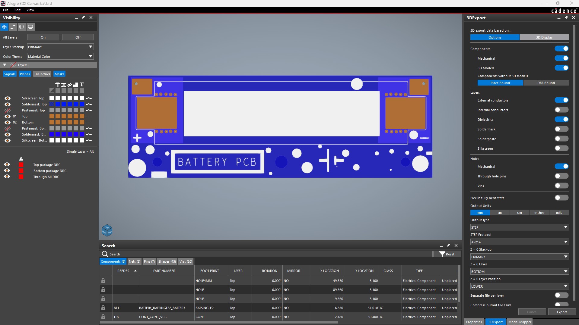
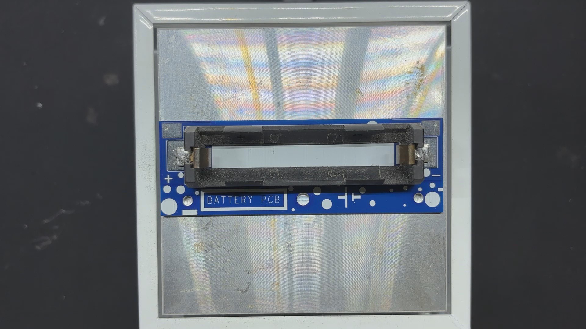
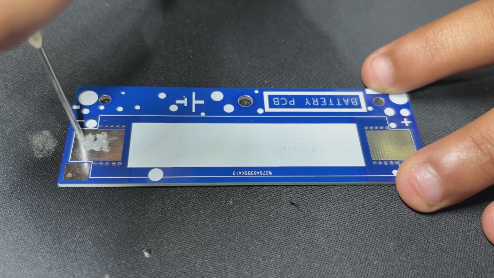
A separate battery board with an SMD lithium cell holder was then added.
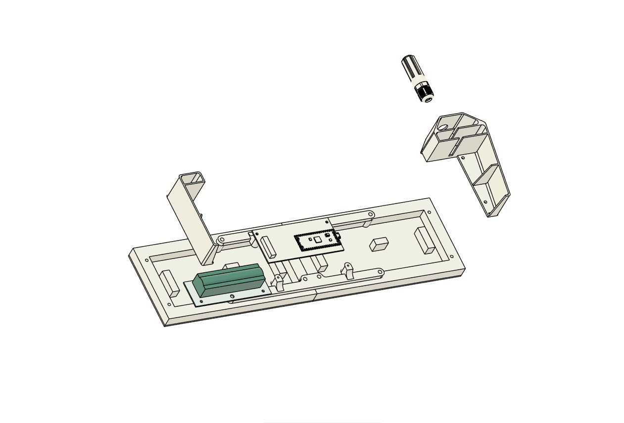
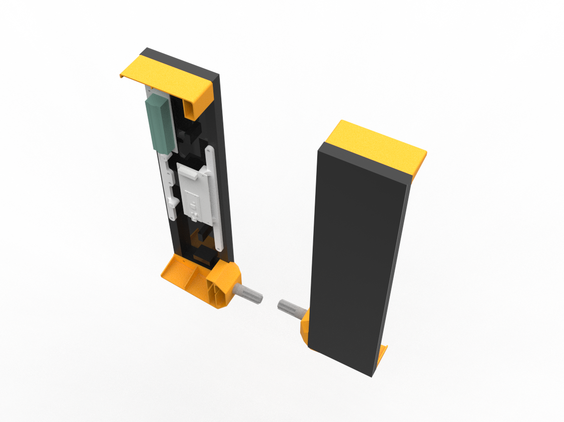
Our objective is to wall-mount the setup vertically, so we modeled two frame-like parts. The top frame part will be used to hang the setup on a wall using nails, and the bottom frame part houses the SGP40 Probe. We also added a circular opening where the PG7 connector can be fastened.
Following model completion, we used our Creality K10 Max to print the Top and bottom frames from orange PLA, while the Matrix holder parts were reused from our previous Snake game Max project.
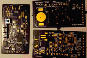
PCB DESIGN


The PCB design process came next, and we began putting together the schematic. There are two main sections in the schematic: the Power section, which included the IP5306 power management circuit, which is a very helpful circuit that I always use in my projects when 5V power is needed. It is dependable, simple to assemble, requires few components, has good efficiency, has battery low- and high-cut features, even has LED fuel indication, and provides stable 5V 2A for driving any 5V device.
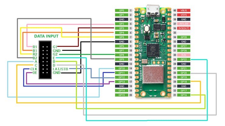
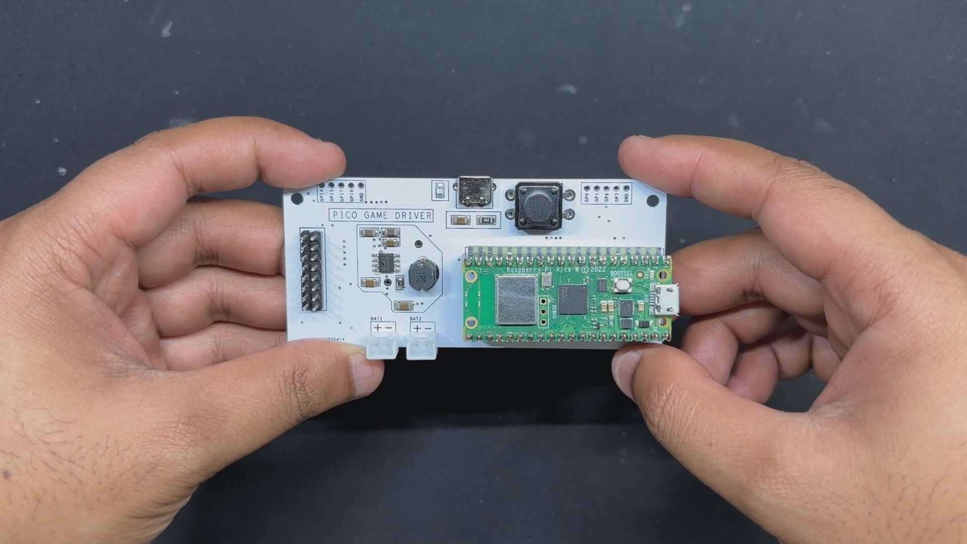
The Matrix will be powered by our beloved Raspberry Pi PICO W, which is coupled to a HUB75 connector in the second section.
We connected the matrix's HUB75 pins (CON 16) to the PICO's GPIO pins in the following order: A to GPIO19, B to GPIO16, C to GPIO18, D to GPIO20, E to GPIO22, CLK to GPIO11, LAT/STB to GPIO12, OE to GPIO13, R1 to GPIO2, G1 to GPIO3, B1 to GPIO4, R2 to GPIO5, G2 to GPIO8, and B2 to GPIO9.
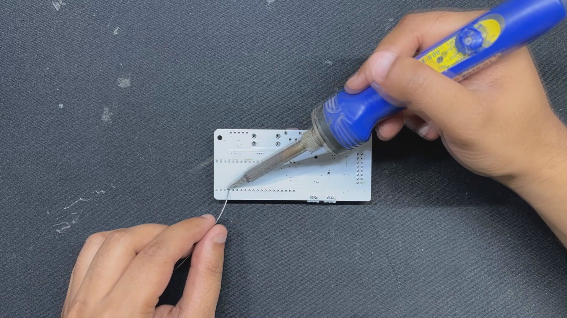
Additionally, we created an additional board that would house the SMD lithium cell 18650 holder. A JST wire harness will connect this board to the driver board's battery connector.
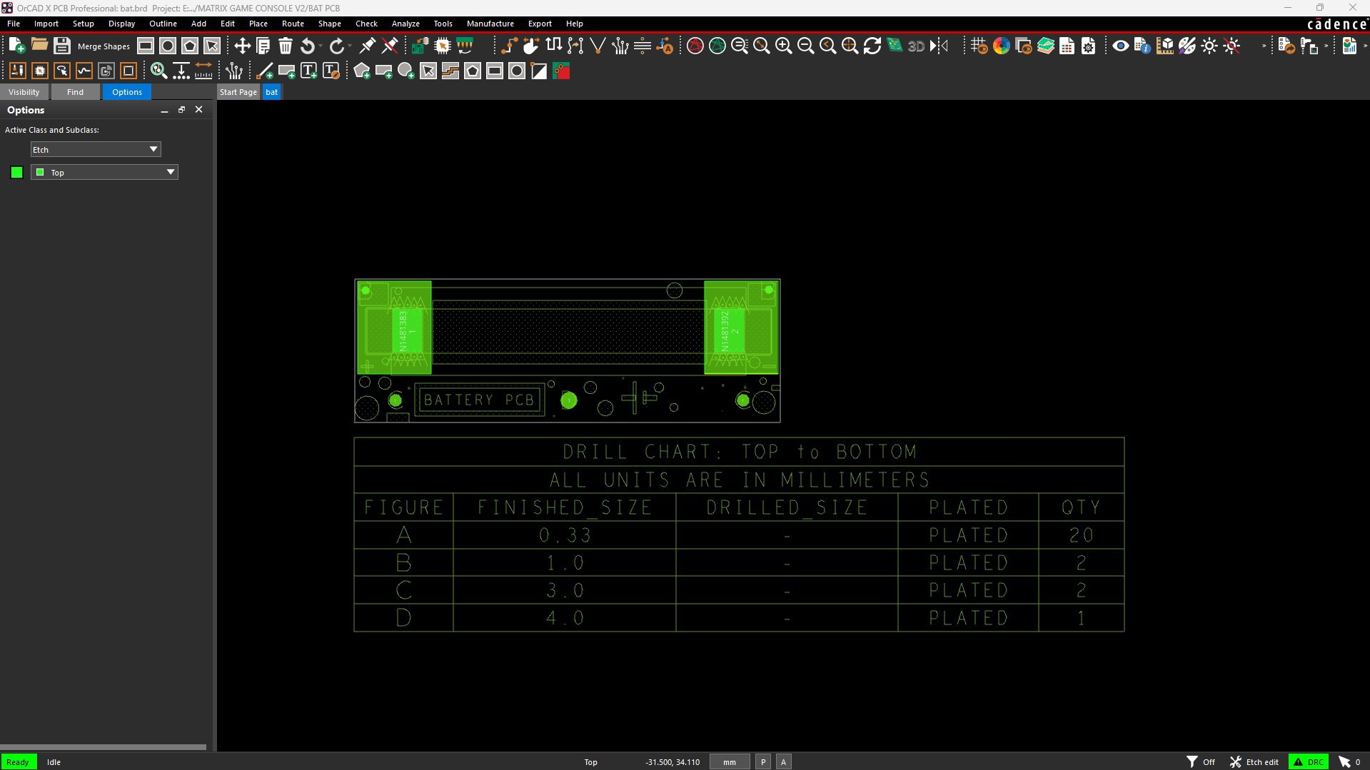
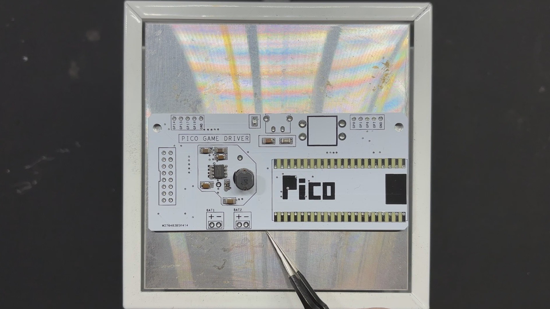
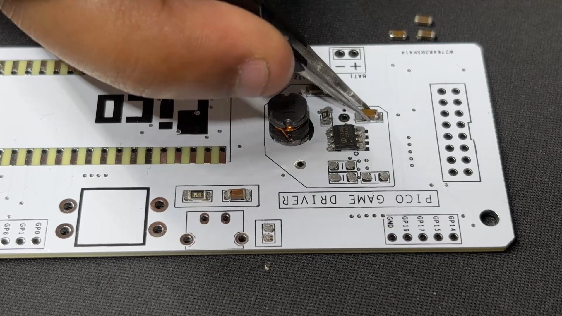
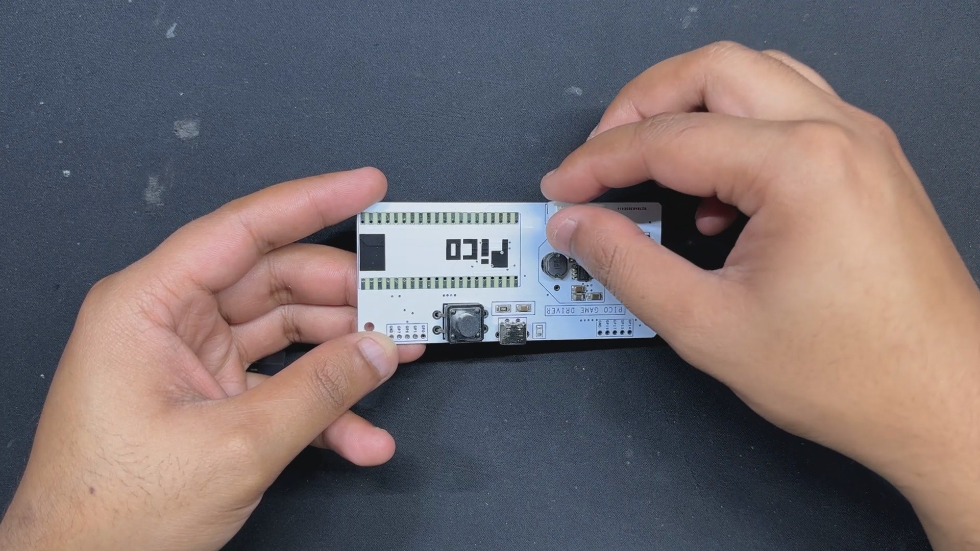
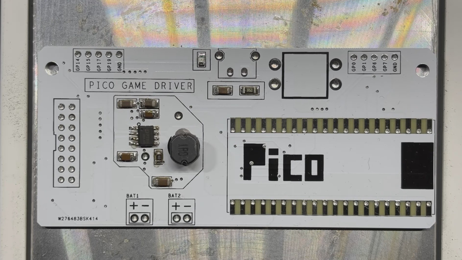
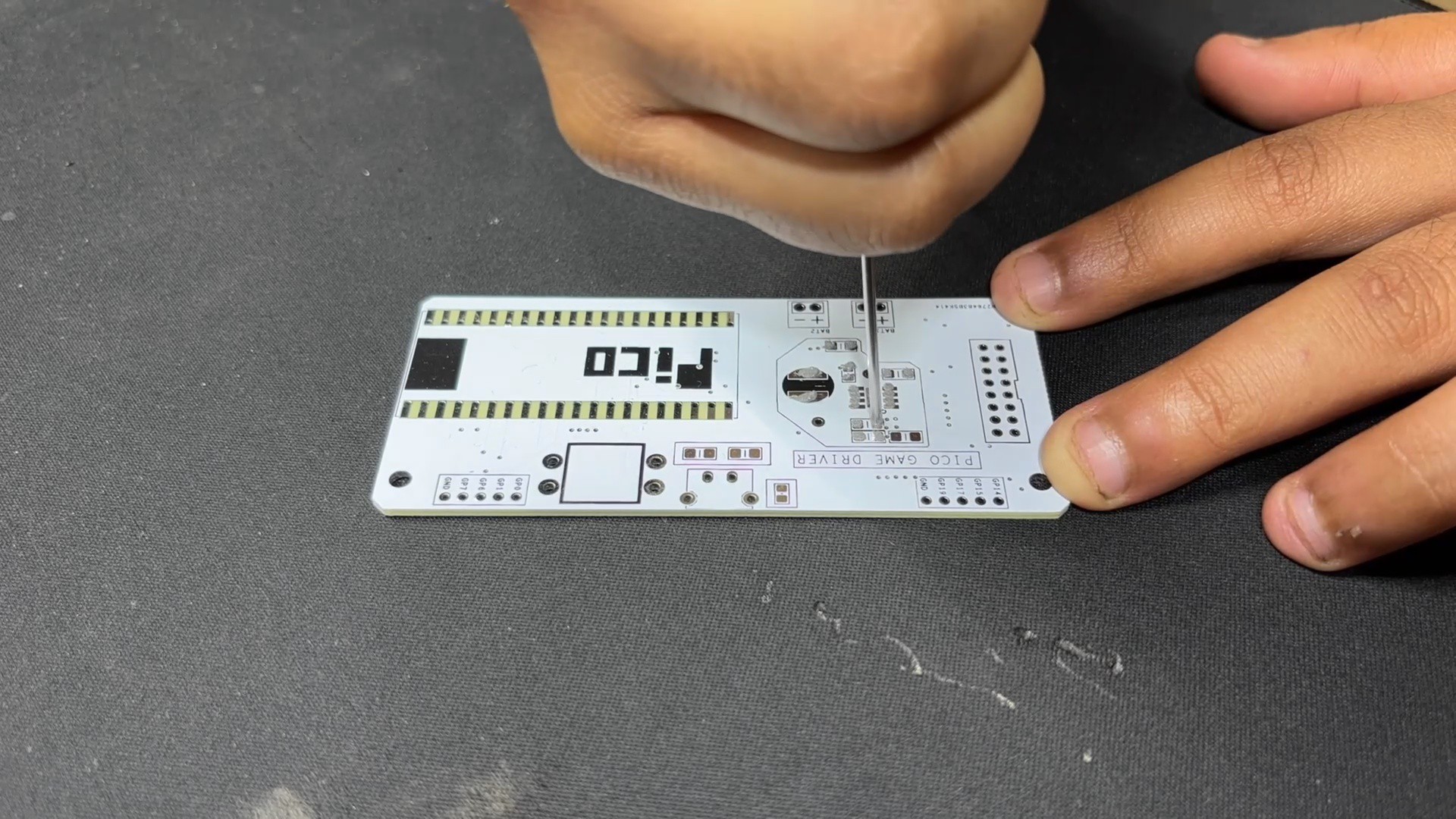
We constructed both PCBs using the dimensions from the Cad model, placing components in their proper...
Read more »


 DIY GUY Chris
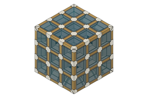
 Will Donaldson
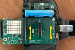
 Zachary Murtishi