 Bertrand Selva
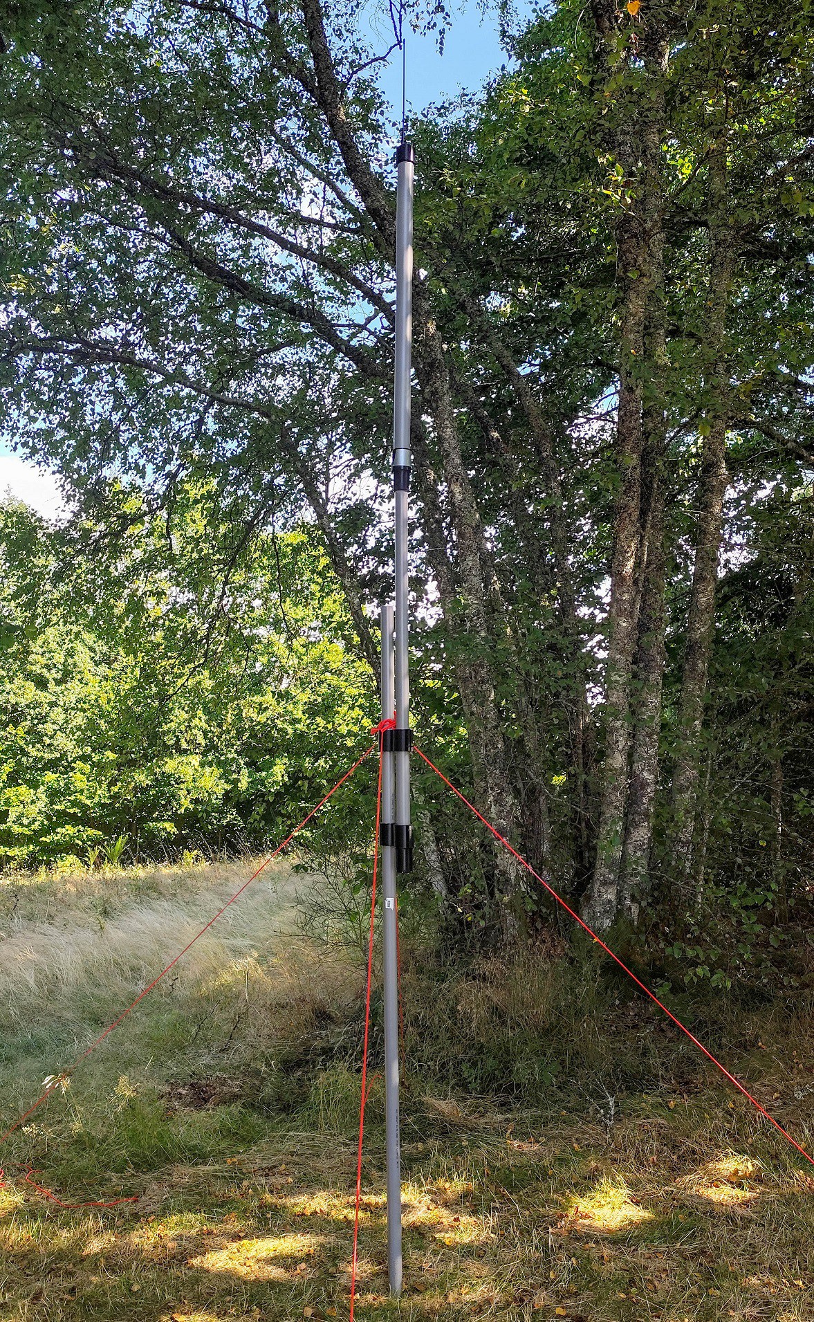
That’s why a repeater is necessary: to fully exploit the available link budget and reach long distances, the transmitter’s location must be carefully chosen. By placing the repeater at a high point — a hill, tower, or treetop with a clear line of sight — a single module can cover several tens of kilometers without exceeding the legally allowed transmission power. This strategy is at the heart of the LoRaTube concept: keeping a compliant, very low-cost, discreet, and autonomous transmitter (> 5 years), while maximizing coverage through optimal placement.
Why LoRaTube?
Because this project does not use solar panels — it relies instead on alkaline batteries housed in a PVC tube. Most LoRa repeaters (whether DIY or commercial) depend on solar panels paired with lithium-ion batteries, MPPT regulators, and charge management circuitry.
This leads to:
-
a high cost (often €150 or more);
-
some mechanical and electronic fragility;
-
a bulky footprint, making the device more visible and attractive to theft;
-
and above all, poor reliability in winter: in temperate climates, solar production can drop fivefold between summer and winter, forcing designers to oversize the system just to maintain basic service.
The goal is to build an ultra-discreet, robust LoRa repeater using widely available and very low-cost materials — specifically alkaline D-size (LR20) batteries and standard 40 mm / 50 mm PVC pipes for the enclosure and mast. The system is designed to run for multiple years in outdoor environments, including locations with no sunlight (under vegetation, in barns, etc.), for under €50 total, including the LoRa module and enclosure.
Note: This is version 1 of the device, and it is not yet final.
It provides around 2 months of autonomy, but it has already helped validate key design choices (mechanical layout, RF range, propagation testing).
A version 2 PCB is currently under development, with improved autonomy and resilience — including a watchdog, hardware timer, and complete shutdown of the Pico and buck converter between active phases.
Feel free to reach out if you have suggestions, improvements, or strong electronics skills — I'd be happy to discuss it.
Note 2: We are currently editing a video showing real-world radio propagation tests with the LoRaTube installed at Suc au May.
👉 It will be added to the logs soon.
______________________________________________________________
🔋 Power Supply
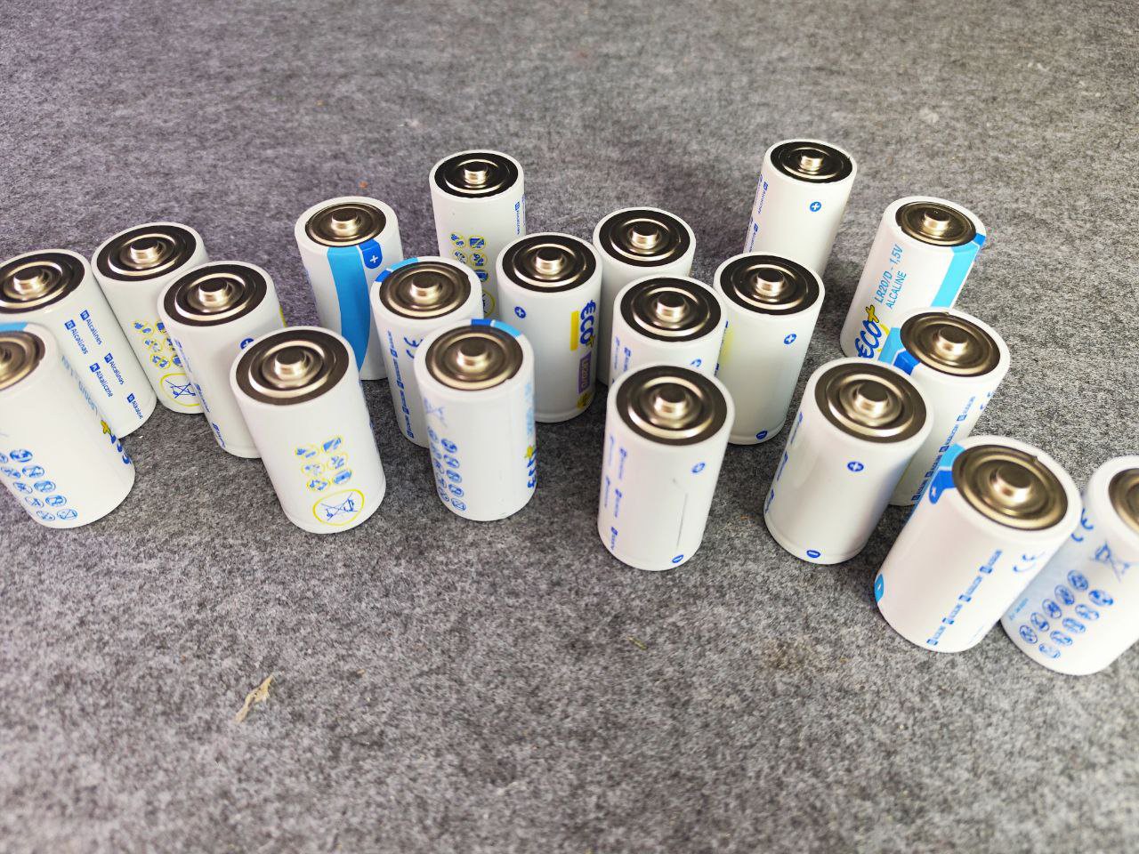
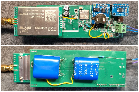
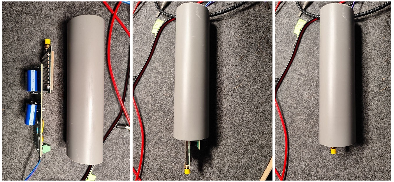
The power supply is based on 18 LR20 alkaline batteries (D size) in series, housed in a compact enclosure less than 50 mm in diameter.
This battery choice offers several practical advantages: LR20 cells are inexpensive (less than €1 each in most supermarkets) and widely available. Each LR20 battery typically provides 12,000 to 18,000 mAh, or 18 to 27 Wh. With 18 batteries, the total energy amounts to approximately 486 Wh, for a total cost of €13.30 (5 packs × €2.66), which translates to just ~€0.024/Wh — a ridiculously low cost compared to lithium alternatives.
For comparison:
-
A 18650 lithium cell offers ~11 Wh for ~€4 → €0.36/Wh (15× more expensive)
-
A pack of ten flat lithium cells (~52 Wh) costs ~€20 → €0.38/Wh
Wiring 18 batteries in series raises the voltage to 27 V (18 × 1.5 V). The cost per delivered kilowatt-hour remains extremely competitive: around €13/kWh, compared to over €250/kWh for a solar + lithium setup (including MPPT regulator) — a 20× cost advantage.
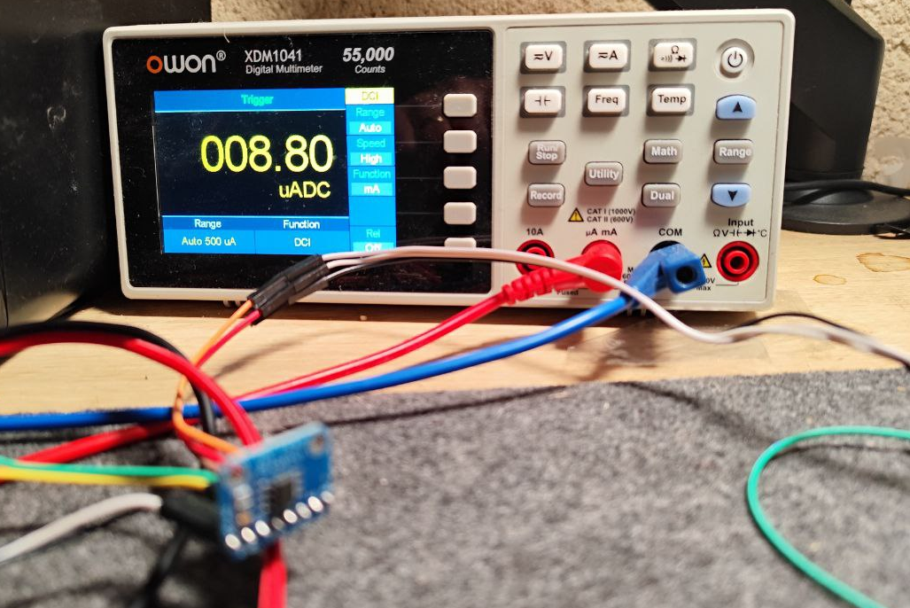
These batteries also have very low self-discharge (< 1% per year), enabling several years of operation as long as the current draw stays low.
Another benefit: the batteries fit neatly inside a standard 40 mm...
Read more »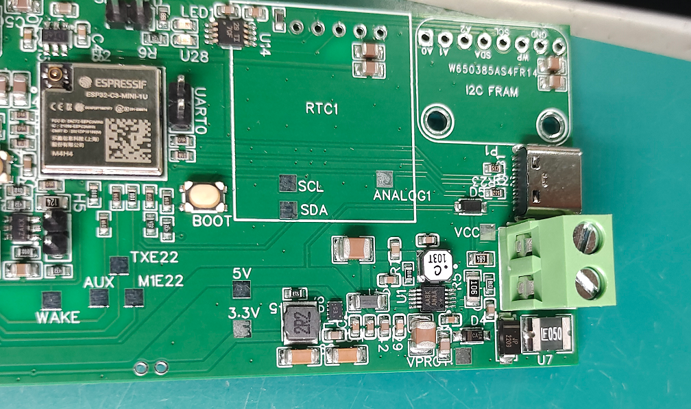
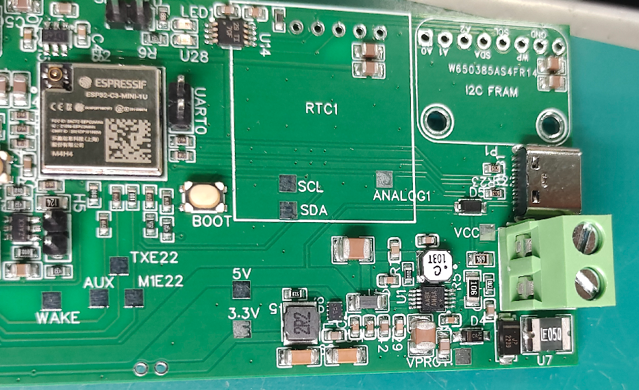
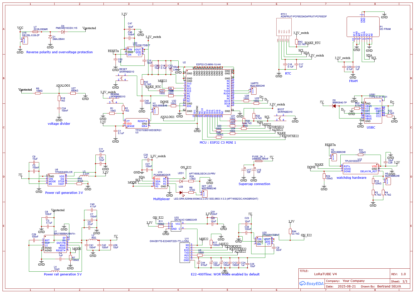
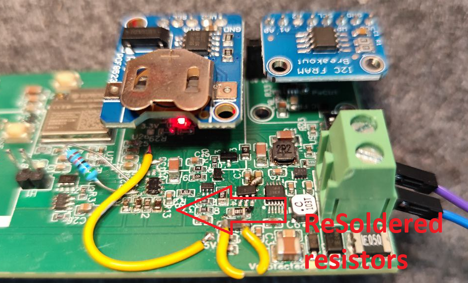
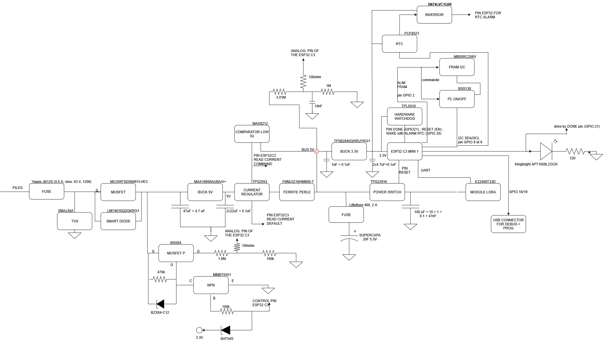
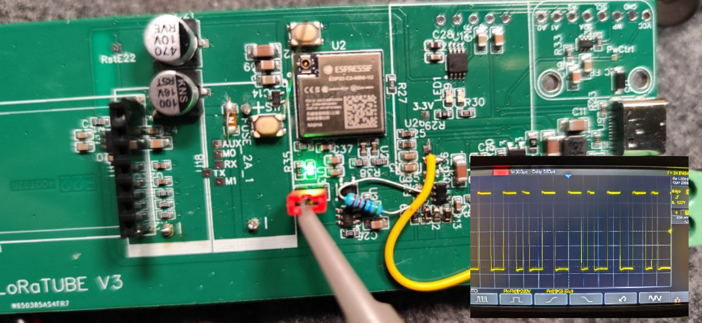 Pin 31 of the ESP32-C3 MCU is TXD0 (U0TXD), which is a UART output (push-pull, idle high, and “talks” at boot and in log mode).
It is impossible to distinguish a true “service dog” activity from simple UART flood: the pin must be changed.
Pin 31 of the ESP32-C3 MCU is TXD0 (U0TXD), which is a UART output (push-pull, idle high, and “talks” at boot and in log mode).
It is impossible to distinguish a true “service dog” activity from simple UART flood: the pin must be changed.


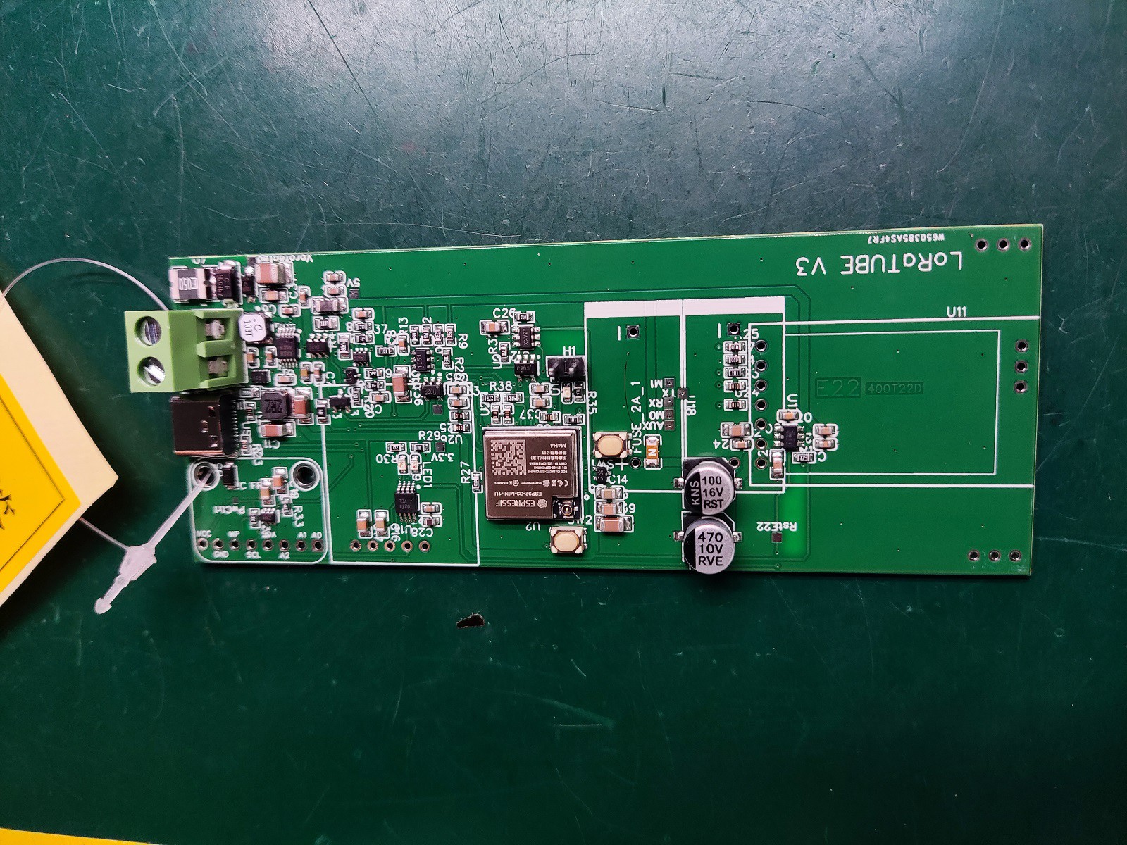

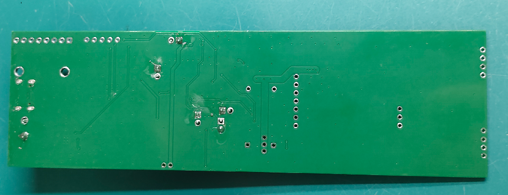
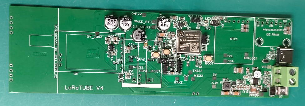
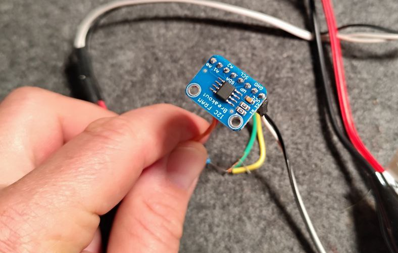
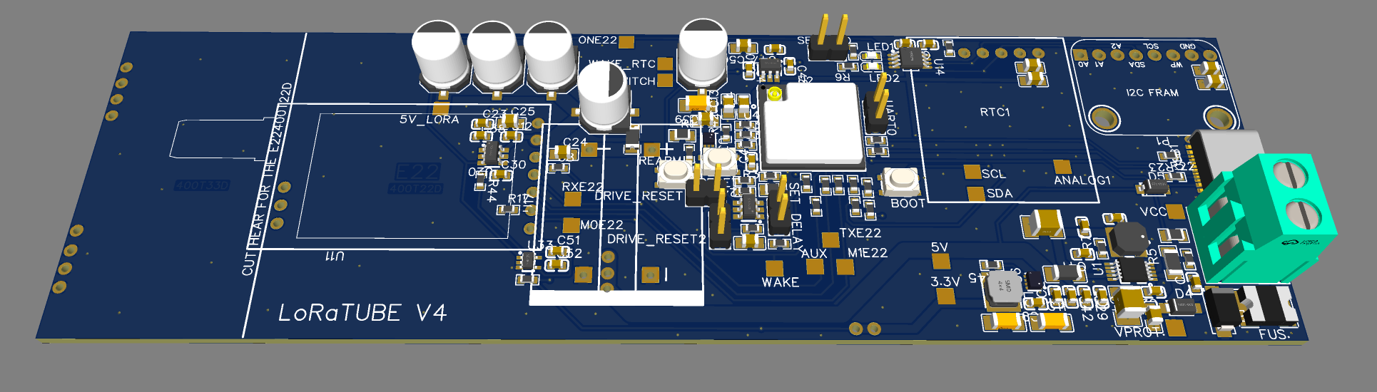
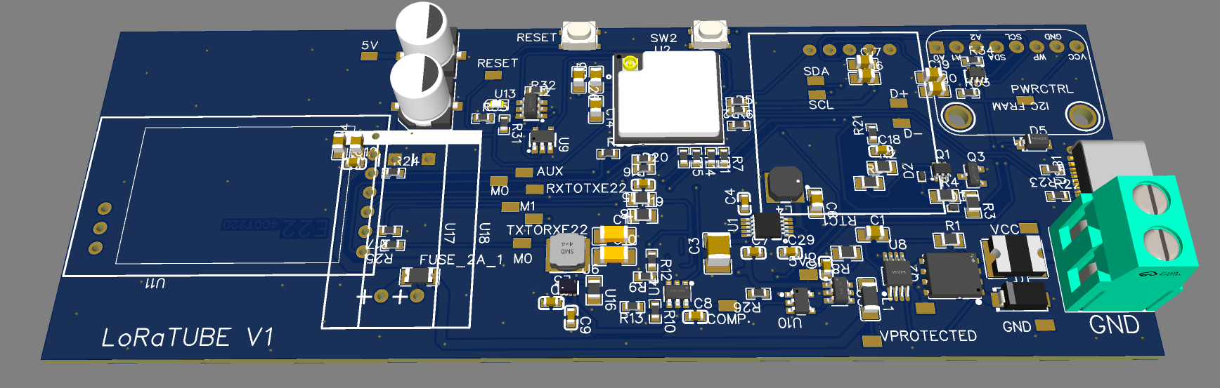 The board is designed to slide into a 50 mm PVC tube. Target outline is 45 mm wide × 125 mm long to leave insertion clearance.

 Jose Ignacio Romero
 Jan Waclawek
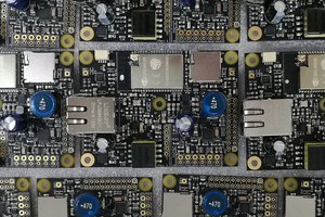
 Patrick Van Oosterwijck
 Clyne
Clyne
Now, as for the topology of your physical transceiver; here I am learning from you Bertrand. I am seeing some very elegant use of iff the shelf modules. I've just gotten into this portion of the project. What I've seen so far makes me want to do a work up if your design on my white board and work through all the calculations that lead your component choices. There's a lot to be learned there.