 Ai-Thinker
The device features the AloT millimeter-wave SoC ICL1112, a high-performance 24GHz single-transmit-single-receive antenna, and peripheral circuitry.
The smart detection algorithm utilizes millimeter-wave distance measurement technology and the ICL1112’s proprietary radar signal processing and power control technology to accurately detect moving, micro-moving, and stationary human presence.
It is designed for indoor applications, operating in low-power mode to determine if there is human activity within the detection area and refreshing the result in real time.
1. Appearance and Pin Descriptions
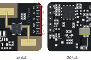
1.1 Appearance
2 Pin Descriptions
Note: Debug and programming interfaces cannot be used simultaneously.
Debug Interface (TTL - USB Debugger)
J2-PIN# | Name | Function | Description |
Pin 5 | OUT | IO output for detection state; HIGH = presence, LOW = no presence | 0~3.3V |
Pin 4 | RX | UART_RX | 0~3.3V |
Pin 3 | TX | UART_TX | 0~3.3V |
Pin 2 | GND | Ground | - |
Pin 1 | 3V3 | Power Input | 3.0~3.6V, Typ. 3.3V |
Programming Interface (J-Link Debugger)
J1-PIN# | Name | Function | Description |
Pin 4 | 3V3 | Power Input | 3.0~3.6V, Typ. 3.3V |
Pin 3 | CLK | SWD Clock Line | 0~3.3V |
Pin 2 | DIO | SWD Data Line | 0~3.3V |
Pin 1 | GND | Ground | - |
2. Using the Rd-03L_V2
2.1 Obtain the PC Software and Related Files
PC software download link: Click to download
2.2 Module Wiring
Wiring between Rd-03L_V2 and TTL converter:
Rd-03L_V2 | USB-TTL Converter |
3V3 | Vo (3V3) |
GND | GND |
TX | RXD |
RX | TXD |
2.3 Module Installation
The Rd-03L_V2 radar should be wall-mounted at a height of 1.5–2 meters. The orientation is illustrated below. X-axis is 0°, Z-axis is 90°, and the Y-axis is perpendicular to the X-Z plane (also referred to as the normal direction).
At 1.5m installation height, the radar’s default maximum detection area is a cone-shaped space of up to 6 meters in the normal direction and ±60° in both horizontal and vertical angles.
2.4 Quick Start with PC Software
Note: The PC software and serial tools cannot be used simultaneously.
After completing wiring (step 2) and installation (step 3), open the PC software to connect the device. Click the refresh button on the bottom left, select the corresponding COM port, set baud rate to 256000, and click Connect Device. Once connected, click Auto Generate Thresholds.
During threshold scanning, ensure the area is completely unoccupied. The scan duration can be set between 120–240 seconds. After scanning, thresholds are automatically applied. Click the top-right corner to close.
After a successful scan, each distance gate’s trigger and hold thresholds will be updated.
Important: Manually adjust the trigger and hold thresholds of distance gates 00 and 01 to around 42 after auto-generation.
This completes the basic threshold configuration.
Additional Settings
- Min/Max Detection Distance: Max = 6.3m
- Distance Report Frequency: 1–8Hz (max: 8Hz)
- Status Report Frequency: Must be a multiple of the distance report frequency (e.g., if distance = 4Hz, status = 4Hz or 8Hz)
- Response Speed: Normal or Fast (transition from "no presence" to "presence")
- No-Presence Delay: Time (10–120s) for switching status from presence to no presence.
After customizing parameters, click Write Sensor Settings to apply them.
2.5 Viewing Data via PC Software
Once configured, click Start in the target info panel to view real-time radar data. The panel shows energy values for each distance gate. When a gate is triggered, its indicator turns red and shows "Presence Detected", along with the distance. The software also estimates average working current.
Higher reporting frequency results in higher current consumption, and vice versa.
3. Power Consumption Measurement
The ultra-low power consumption of the Rd-03L_V2 is achieved by adjusting the reporting...
Read more »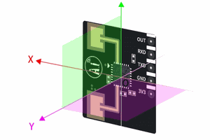
 Bertrand Selva