 Rhea Rae
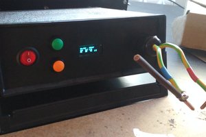
The Ambient Energy Field Converter (AEFC) is an experimental platform for capturing and converting ambient energy from Earth’s ground potential, local electromagnetic fields, and other passive sources. By combining custom coil configurations, capacitive components, and nonlinear circuit behavior, the AEFC investigates how subtle environmental energies can be harvested, stored, and made useful, especially in ultra-low-power applications.
Unlike conventional energy harvesters, the AEFC exhibits dynamic, field-reactive behavior. Voltage levels fluctuate in response to environmental changes, human proximity, and even direct touch, suggesting a capacitive coupling mechanism at work. These emergent responses offer a new direction for ambient energy exploration, circuits that don’t just harvest energy, but interact with their surroundings. AEFC remains in active development, with discoveries driven by hands-on experimentation and intuitive systems thinking.
The component lists is not exhaustive. The project is in active development, with discoveries emerging through direct experimentation and iterative design.


 kevarek
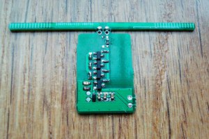
 Jurist
 Simon Merrett
What are you using for diodes? I worked on a project vaguely similar to this in 1999, and the key to my success was using ultra-low-capacitance RF diodes. You are lucky that low-startup-voltage SMPS chips are available now that didn't exist 25 years ago.