 Tom Nardi
This SAO was intended to be used for the 2024 Supercon SMD soldering challenge, but in the mad rush to finish the design and get the PCBs made before the event, I somehow managed to invert the power and ground pins for the ATtiny85. Unfortunately, the mistake went unnoticed until somebody tried to solder one up in Pasadena and the chip started getting toasty. Oops.

As luck would have it, the folks at Supplyframe had made their own SMD Challenge SAO, which is what we ended up using for the competition. But that still left me with 150+ little reminders of my own hubris.
I very nearly threw them all away before getting on the plane back to the East Coast, but at the last minute, decided to take a few bags of them home with me. I've since handed a few of them out at different events, so if you find yourself in possession of one, you have a rare bit of Hackaday memorabilia on your hands.

 David
David
 Tindie
 Dávid Máté
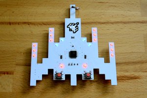
 Mike Szczys