 Tony Keith
The Input Commands:
I wanted to use a 4 x 4 (16) button key pad to input all the commands with a simple / easy to remember protocol (format).
Here is the basic command format:
Channel@Intensity
Start Channel-End Channel@ Intensity
Here is the actual input protocol using only a 4 x 4 (16) button key pad:
| Command | Description |
| XXX@III# | Single Channel at a Specified Intensity |
| XXX-XXX@III# | Range of Channels at a Specified Intensity |
| *@*# | All Channels at Full Intensity |
| XXX@*# | Single Channel at Full Intensity |
| XXX-*@III# | Start Channel to Max Channel at a Specified Intensity |
| XXX-*@*# | Start Channel to Max Channel at Full Intensity |
Legend:
* = Wildcard value: 512 for channel and 256 for Full intensity
XXX = 1 to 512 Channel Number
III = 1 to 256 Intensity Level
Key Mappings:
A = @ (at sign)
B = Bump (not implemented)
D = - (dash)
C = Clear
# = Execute
Code Development / Testing:
I developed / tested the code in several stages:
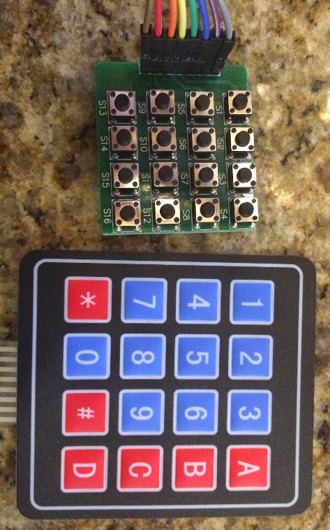
- Keypad input - 4 x 4 (16) button key pad (or switch array)
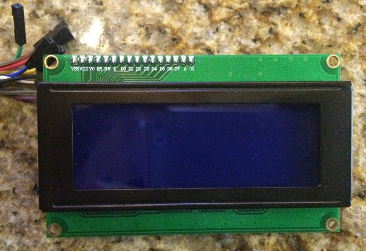
- LCD display - 4 x 20 Character LCD w I2C interface
- Verify/test the input commands (protocol) were working correctly
- Add DMX master (sending) code
The Keypad
Hardware:
I had 3 types of key pads that I played with (switches on a PC board, membrane switch, soft-touch)
See the pictures of the keypads I used.

Software:
I started with the Keypad library for easy matrix style keypad mapping. See http://playground.arduino.cc/code/Keypad for more information.
I had to play around with the Row and Column mapping to get my Key Pad switch matrix to work. The pin-out in the documentation wasn't correct on any of the keypads. So once I determined the correct pin-out, the code worked perfectly.
Here is code snippet showing how to use the Keypad library:
(This is for the 16 switches on PC board)
#include <Keypad.h>

const byte ROWS = 4; // define four rows
const byte COLS = 4; // define four columns
char keys [ROWS] [COLS] = {
{'1', '2', '3','@'},
{'4', '5', '6','B'},
{'7', '8', '9','C'},
{'*', '0', '#','-'}
};

// Pin  R/C
// 8    C4
// 7    C3
// 6    C2
// 5    C1
// 4    R1
// 3    R2
// 2    R3
// 1    R4

// Connect 4 * 4 keypad row-bit port, the corresponding digital IO ports panel
byte rowPins [ROWS] = {6,7,8,9};

// Connect 4 * 4 buttons faithfully port, the corresponding digital IO ports panel
byte colPins [COLS] = {10,11,12,13};

// Call the function library function Keypad
Keypad keypad = Keypad (makeKeymap (keys), rowPins, colPins, ROWS, COLS);

void loop () {

  char key = keypad.getKey ();
  if (key != NO_KEY) {

    // Clear
    if(key == 'C') {
      state = CLEAR;
    }
}
The LCD display
Hardware:
I used a standard 4x20 character display with I2C (serial) interface which can be purchased from Ebay for about $10.00.
Software:
I started with a I2C LCD display library. See LiquidCrystal_I2C Library
for more information.
I really didn't have any problems getting the display to work. The 2x16 character display included in my Arduino kit didn't work so I ordered a 4x20 character display and it worked the first time I tried it.
Here is a code snippet showing how to use the LiquidCrystal_I2C library:
#include <LiquidCrystal_I2C.h>

LiquidCrystal_I2C lcd(0x3F,20,4);

void setup () {
  lcd.init();
  lcd.backlight();
  lcd.setCursor(0,0);
  lcd.print("DMX Tester ");
  lcd.print(VERSION);
  lcd.setCursor(0,1);
  lcd.print("Enter Cmd:");
}
The Input Protocol (Commands)
At first I was going to use a state machine logic to handle the input from the keypad but I decided to try to just code it with normal logic. After writing the initial version, I spent about 4 or 5 hours debugging the code. I soon realized I should have created a state diagram and used state driven logic. to parse the input properly.
So I deleted most of the code and wrote a test plan and state diagram to match the input protocol.
Here is the test plan with all the input protocols defined: DMX Tester Test Plan
and here is the state diagram: DMX Tester State Diagram
Once I have the state diagram completed, I coded the input part of...
Read more »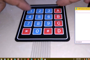

 Cees Meijer
 Mark VandeWettering
 John Anderson